Using Intelligent Output Terminals
Oper
ations
a
nd Moni
tor
ing
4–50
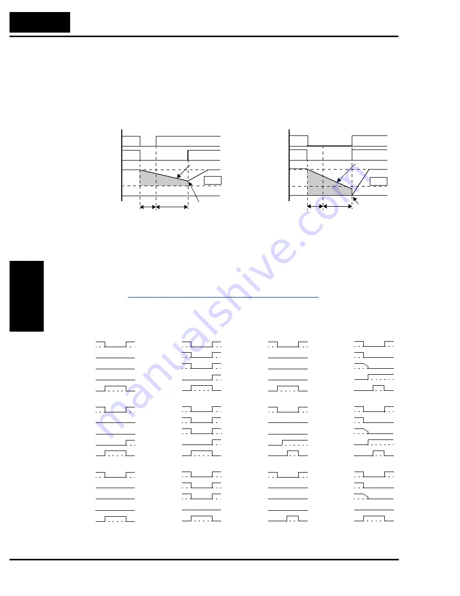
Examples 3 and 4 relate to configuring the inverter to retry upon power failure. Frequency
matching is possible if the inverter frequency is greater than the B007 value. In this case, the
inverter reads the motor RPM and direction. If this speed is higher than the matching setting
(B007), the inverter waits until they are equal and then engages the output to drive the motor
(example 3). If the actual motor speed is less than the restart frequency setting, the inverter
waits for t
2
(value in B003) and restarts from 0 Hz (example 4). The display shows “
0000
”
during an actual frequency matching event.
The Instantaneous Power Failure and Alarm output responses during various power loss condi-
tions are shown in the diagram below. Use B004 to enable/disable the alarm output when
instantaneous power failure or under-voltage occurs. The alarm output will continue while the
control power of the inverter is present, even if the motor is stopped. Examples 5 to 7
correspond to normal wiring of the inverter’s control circuit. Examples 8 to 10 correspond to
the wiring of the inverter’s control circuit for controlled deceleration after power loss (see
“Optional Controlled Decel and Alarm at Power Loss” on page 4–4
).
Power supply
Inverter output
Motor
frequency
Motor frequency > B007 value at t
2
Example 3: Motor resumes via frequency-matching
Example 4: Motor restarts from 0Hz
t
0
t
2
Power supply
Inverter output
Motor
frequency
t
0
t
2
Free-run
Free-run
Frequency matching
0Hz restart
Motor frequency < B007 value at t
2
B007
B007
t
t
Instantaneous power failure operation with standard
R0–T0 connections
Instantaneous power failure operation with R0–T0
connected to P–N
Example 5
Power
1
0
1
0
Run command
Output
Alarm
Inst. Power Fail
1
0
1
0
Inverter : Stop
Example 6
Power
1
0
1
0
Run command
Output
Alarm
Inst. Power Fail
1
0
1
0
Inverter : Stop
1
0
1
0
1
0
1
0
Power
Run command
Output
Alarm
Inst. Power Fail
Example 7
Inverter : Stop
Power
1
0
1
0
Run command
Output
Alarm
Inst. Power Fail
1
0
1
0
Inverter : Run
Power
1
0
Run command
Output
Alarm
Inst. Power Fail
1
0
1
0
Inverter : Run
1
0
1
0
1
0
1
0
Power
Run command
Output
Alarm
Inst. Power Fail
Inverter : Run
1
0
Example 8
Power
1
0
1
0
Run command
Output
Alarm
Inst. Power Fail
1
0
1
0
Inverter : Stop
Example 9
Power
1
0
1
0
Run command
Output
Alarm
Inst. Power Fail
1
0
1
0
Inverter : Stop
1
0
1
0
1
0
1
0
Power
Run command
Output
Alarm
Inst. Power Fail
Example 10
Inverter : Stop
Power
1
0
1
0
Run command
Output
Alarm
Inst. Power Fail
1
0
1
0
Inverter : Run
Power
1
0
Run command
Output
Alarm
Inst. Power Fail
1
0
1
0
Inverter : Run
1
0
1
0
1
0
1
0
Power
Run command
Output
Alarm
Inst. Power Fail
Inverter : Run
1
0
(under-voltage)
Содержание SJ700-004LFU2
Страница 2: ......
Страница 42: ......
Страница 162: ......
Страница 241: ...Inverter System Accessories In This Chapter page Introduction 2 Component Descriptions 3 Dynamic Braking 6 5 ...
Страница 248: ......
Страница 278: ......
Страница 279: ...Glossary and Bibliography In This Appendix page Glossary 2 Bibliography 6 A ...
Страница 359: ...Drive Parameter Settings Tables In This Appendix page Introduction 2 Parameter Settings for Keypad Entry 2 C ...
Страница 378: ......
Страница 390: ......


