“P” Group: Expansion Card Functions
Configur
ing Dr
iv
e
P
a
ra
meters
3–72
Absolute Position
Control Mode
To use the absolute position control mode, set A044 V/F characteristic curve setting (1st motor)
equal to “02” (V2) and set P012 Control Pulse Setting equal to “02” APR – Automatic Position
Control Mode.
• If P012 = 03 (high-resolution absolute position control, the inverter quadruples the number
of pulses used for positioning. In this case multiply the multistage position settings and
position ranges by four.
• Position settings can be sequenced in up to eight stages in combination with control pulse
settings. You can select zero-return mode from one low-speed and two high-speed modes.
(The home search function cannot be used during a zero-return.)
• The teaching function allows you to set (store) position settings while actually running the
machine (motor is turning).
• If intelligent terminal [SPD] Speed/position Control Select (option code 73) is assigned, you
can switch between speed control and position control.
• Only the four high-order digits of data are displayed when the data (position setting) to be
displayed consists of a large number of digits.
In Absolute Position Control Mode, the inverter runs the motor until the machine reaches the
target position according to the following settings, and then set the machine into the position
servo-lock state (until the Stop Command occurs):
1.
Position setting
2.
Speed setting (output frequency)
3.
Acceleration and deceleration time
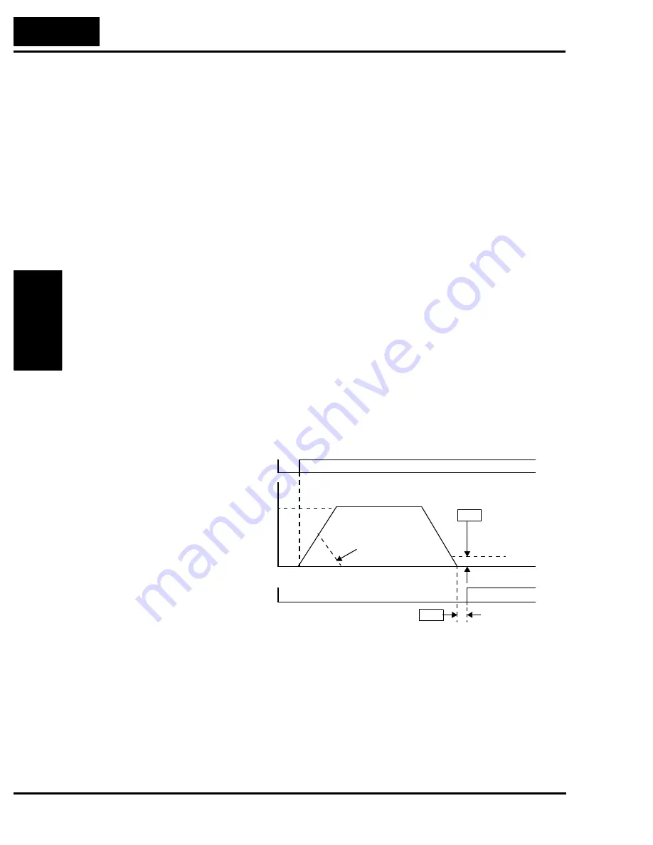
In absolute position control mode, the frequency and accel/decel settings selected at absolute
position control are applied. If the position setting value is small, the inverter may decelerate
the motor for positioning before its speed reached the set speed setting. In absolute position
control mode, the direction of the operations command (forward or reverse) is ignored. The
operation command simply functions as a signal to run or stop the motor. Motor direction is
determined by the algebraic sign of the difference between the current position and the target
position.
If zero return operation as described below is not performed, the motor position detected at
powerup is assumed to be at the origin (position data = 0). When the operation commend is
turned ON with zero specified as the position setting, positioning is completed without running
the motor.
Set C102 Reset Mode Selection = 03 so that the inverter only resets a trip condition (does not
turn OFF the motor output). Otherwise, the current position counter is cleared when the inverter
reset terminal turns ON. Be sure to set C102 = 03 if you intend to use the value of the current
position counter for operation after recovering the inverter from a trip by turning ON the reset
terminal (reset key).
Output frequency
[POK]
0
Small position value
causes decel before
target speed is reached
P017
Operation command
Speed setting
P018
Position
Home search
completion range
setting
Home search completion
delay time setting
0
1
Содержание SJ700-004LFU2
Страница 2: ......
Страница 42: ......
Страница 162: ......
Страница 241: ...Inverter System Accessories In This Chapter page Introduction 2 Component Descriptions 3 Dynamic Braking 6 5 ...
Страница 248: ......
Страница 278: ......
Страница 279: ...Glossary and Bibliography In This Appendix page Glossary 2 Bibliography 6 A ...
Страница 359: ...Drive Parameter Settings Tables In This Appendix page Introduction 2 Parameter Settings for Keypad Entry 2 C ...
Страница 378: ......
Страница 390: ......


