--- 28 ---
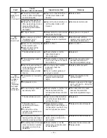
Adjuster (B)
[39]
Roll Pin D3 x 18
[34]
O-ring (P-4)
[36]
Guide Shaft
[33]
Vertical Guide
[35]
Pushing Lever Spring
[37]
Steel Ball D3.175
[41]
Adjuster Spring
[40]
Spring
[32]
Adjuster Stopper
[25]
Feeder Arm
[28]
Body Ass'y
[20]
O-Ring (1AP-3)
[24]
Roll Pin D4 x 14
[26]
Hex. Socket Hd.
Bolt M6 x 20
[31]
Needle Roller
[27]
Feeder Spring
[29]
Feeder
[30]
Pushing Lever (B)
[38]
Pushing Lever (A)
[42]
Hex. Socket Hd. Bolt M6 x 14
[44]
Washer
[43]
Nose
[69]
Feed Piston Cover
[75]
Feed Piston
[72]
Retaining Ring for
D28 Hole
[77]
Magazine Bushing
[76]
Bumper
[74]
Feed Spring
[73]
O-ring (1AP-20)
[71]
O-ring (P-9)
[70]
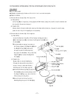
9-5. Disassembly and Reassembly of Nail Feeder Section
Fig. 21 Disassembly and reassembly of nail feeder section
Tools required
5 mm hexagon bar wrench
4 mm dia. roll pin remover
C-type retaining ring puller
Flat-blade screwdriver
(1) Disassembly and reassembly of the Nose
[69]
, Pushing Lever (B)
[38]
, Pushing Lever
(A)
[42]
and related parts (See Fig. 21.)
(a) Disassembly:
Remove the Hex. Socket Hd. Bolt M6 x 20
[31]
, and extract the Roll Pin D3 x 18
[34]
.
The Nose
[69]
and the pushing lever
components can then be taken off.
Remove the Hex. Socket Hd. Bolt M6 x 14
[44]
, and take off Adjuster (B)
[39]
and
Pushing Lever (A)
[42]
.
(b) Reassembly:
Proceed in reverse to the disassembly procedure, taking care of the following points.
Prior to reassembly, apply grease to the Adjuster Spring
[40]
.
When reassembling the Nose
[69]
, be very careful not to forget to install the Adjuster Stopper
[25]
in the
4.4 mm dia. hole between the Nose
[69]
and the Body Ass'y
[20]
.
After reassembly, confirm that the pushing lever components and Adjuster (B)
[39]
operate smoothly.
Содержание NV 50AG2
Страница 39: ......


