--- 22 ---
9-2. Disassembly and Reassembly of the Output Section
(1) Disassembly and reassembly of the Exhaust Cover
[4]
, Head Valve (A)
[8]
, Piston
[12]
, Cylinder
[16]
and
related parts:
Hex. Socket Hd. Bolt
M5 x 35
[2]
Exhaust Cover
[4]
Top Cover
[1]
Head Valve Spring
[6]
Cylinder Packing
[13]
Body Ass'y
[20]
Body Ass'y
[20]
4 mm dia. bosses
of the Cylinder
Packing
[13]
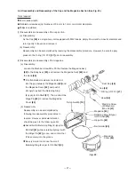
Fig. 10 Disassembly and reassembly of piston,
cylinder and exhaust cover
Tool required
4 mm hexagon bar wrench
(a) Disassembly (See Fig. 10.)
Loosen the four Hex. Socket Hd. Bolts M5 x 35
[2]
, and
remove the Exhaust Cover
[4]
. The Piston
[12]
, Cylinder
[16]
,
Piston Bumper
[17]
and related parts that make up the output
section can then be taken out.
As the Top Cover
[1]
is press-fitted into the groove at the upper
part of the Exhaust Cover
[4]
, it can be removed by inserting
an appropriate rod into the exhaust port.
As the Cylinder Packing
[13]
is fitted into the groove of the
Cylinder
[16]
by a pliable rubber fit, simply bend the rubber
enough to slide over the side of the groove so that it can be
taken out.
(b) Reassembly
Reassembly can be accomplished by following the
disassembly procedures in reverse. However, particular
attention should be given to the following points.
When reassembling Cylinder Washer (A)
[14]
and Cylinder
Packing
[13]
onto the Cylinder
[16]
, assemble them so that the
curved portion of Cylinder Washer (A)
[14]
is on the Piston
Bumper
[17]
side.
Fig. 11
Gasket (A)
[5]
Head Valve O-Ring
[7]
Head Valve (A)
[8]
Piston Ring
[9]
Piston O-Ring
[10]
Piston
[12]
O-Ring (P-32)
[15]
Cylinder Washer (A)
[14]
Cylinder
[16]
Piston Bumper
[17]
Body ribs
Fig. 12
Set the curved portion
(protruding side) to the
side of the Piston
Bumper
[17]
4.5 mm dia. hole
of Cylinder
Washer (A)
[14]
Curved portion of
Cylinder Washer
(A)
[14]
Cylinder
[16]
groove
Bumper (A)
[11]
Содержание NV 50AG2
Страница 39: ......


