background image

--- 20 ---

Abnormal O-ring (I.D 37.2) 

[47]

 (worn, broken or scratched)

Loose Cap 

[48]

 fastening threads

Abnormal Body Ass'y 

[20]

 and Cap 

[48]

 seal surfaces (damaged, deformed  or

scratched)

Air leakage portion

 D  Nose 2

Cause

When the trigger is turned off

When the trigger is turned on

* Incorrect assembly of Cylinder

Washer (A) 

[14] 

or Cylinder Packing

[13]

Abnormal sealed surfaces of Cylinder
Packing 

[13]

, Body Ass'y 

[20]

 or

Cylinder 

[16] 

(sections  c  and  d )

Abnormal Valve Piston (B) 

[63]

,

O-ring (I.D 11) 

[64]

 (worn, broken or

scratched)
Abnormal Valve Piston (B) 

[63]

,

O-ring (I.D 8.8) 

[61]

 (lower side)

(worn, broken or scratched)
Abnormal Valve Bushing (B) 

[59]

,

Head Valve O-ring (I.D 16.8) 

[58]

.

(broken or scratched)

* Abnormal Body Ass'y 

[20]

 valve

chamber inner surface (section  i  )

Abnormal Piston Bumper 

[17]

(sections  e ,  f  deformed or cracked)
Deformation of Piston 

[12]

 (deformed

driver blade, abnormal sealed
surface)
Deformed section  f  of Body Ass'y 

[20]

.

Worn, deformed, broken or scratched
O-ring (S-12) 

[21]

.

 E  Feed piston

 F  Control valve 1

Abnormal Feed Piston 

[72]

, O-ring

(1AP-20) 

[71]

 (worn, broken or

scratched), or the O-ring sliding
surface on the Nose 

[69]

 is worn,

deformed or scratched.
Abnormal Nose 

[69]

, O-ring (P-9)

[70]

 (worn, broken or scratched), or

the O-ring sliding surface on the feed
piston is worn, deformed or
scratched.

 G  Control valve 2

Abnormal Valve Piston (B) 

[63]

,

O-ring (I.D 8.8) 

[61]

 (upper side)

(worn, broken or scratched)
Abnormal Valve Bushing (B) 

[59]

,

Head Valve O-ring (I.D 16.8) 

[58]

.

(broken or scratched)

* Abnormal Body Ass'y 

[20]

 valve

chamber upper surface (section  h )

 H  Cap

Abnormal Plunger (A) 

[66]

, O-ring

(I.D 1.8) 

[67]

 (lower side)  (worn,

broken or scratched)
Abnormal Valve Bushing (A) 

[68]

(deformed or scratched plunger
sliding surface)

Abnormal Plunger (A) 

[66]

, O-ring

(I.D 1.8) 

[67]

 (upper side) (worn,

broken or scratched)
Abnormal Valve Piston (B) 

[63]

(deformed or scratched plunger
sliding surface)

Содержание NV 50AG2

Страница 1: ...TECHNICAL DATA AND SERVICE MANUAL COIL NAILER NV 50AG2 SPECIFICATIONS AND PARTS ARE SUBJECT TO CHANGE FOR IMPROVEMENT LIST No E020 Jan 2005 N MODEL NV 50AG2 Hitachi Power Tools ...

Страница 2: ...CIPLE 11 7 1 Mechanism 11 7 2 Operation Principle 12 8 TROUBLESHOOTING 14 8 1 Troubleshooting and Correction 14 8 2 Possible Causes and Corrections for Air Leakage 19 9 DISASSEMBLY AND REASSEMBLY 21 9 1 General Precautions in Disassembly and Reassembly 21 9 2 Disassembly and Reassembly of the Output Section 22 9 3 Disassembly and Reassembly of the Control Valve Section 24 9 4 Disassembly and Reass...

Страница 3: ...nt functions such as the vertical nailing guide mechanism 3 APPLICATIONS Installation of plaster board and similar materials in interior construction 4 SELLING POINTS Lightweight 1 4 kg 3 1 lbs One touch 360û exhaust direction control Ergonomically designed grip Change knob for 2 model drive control Continuous shot and single shot modes Nailing depth adjustment mechanism Vertical nailing guide mec...

Страница 4: ...odel NV 50AG2 equipped with a unique vertical nailing guide mechanism drives nails more vertically into the surface of plaster board than is possible with conventional nailers Conventional nailer mechanism Model NV 50AG2 mechanism Plaster board Nail is inclined inside nail output guide Nail is driven in inclined condition Vertical nailing guide mechanism Paper covering of plaster board is damaged ...

Страница 5: ...adjust both the air pressure used and the adjuster Turn the adjuster to the deepest point Set the air pressure used to 4 9 bar 5 kgf cm2 70 psi as a guide Carry out test driving If the nail depth is too deep turn the adjuster to the shallow side If the nail depth is too shallow adjust the air pressure used to the higher Too deep Turn the adjuster to the shallow side Deep Shallow Adjuster ...

Страница 6: ... Package dimensions Length x Height x Width Standard accessories Optional accessories NV 50AG2 Reciprocating piston type 4 9 8 3 bar 5 8 5 kgf cm2 70 120 psi Gauge pressure 3 pcs sec 1 4 kg 3 1 lbs 243 mm L x 288 mm H x 125 mm W 9 9 16 x 11 11 32 x 4 15 16 Reciprocating piston type 0 80 liter cycle at 6 9 bar 0 80 liter cycle at 7 kgf cm2 0 28 ft3 cycle at 100 psi NPT 3 8 thread Corrugated cardboa...

Страница 7: ...iled as shown in Fig 2 NOTE There are nails very similar to those illustrated below in local markets However since dimensions other than those shown will cause jamming faulty nail feeding and or damage to the tool mechanism it is important that the customer be cautioned to ensure that only Hitachi approved nails are utilized 7 0 mm 273 7 0 mm 273 2 5 mm 098 2 3 mm 091 32 mm 1 1 4 45 mm 1 3 4 7 0 m...

Страница 8: ...32 45 1 1 4 1 3 4 118 4 646 Unit mm inch d D2 H 2 39 2 5 091 098 52 2 047 20 787 The nail connecting dimensions and coil sizes after winding are shown below Sheet collated nails Fig 2 Collated and coiled nails ...

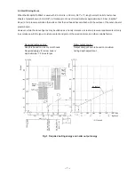
Страница 9: ...r while the above figures may be utilized as a handy reference actual air pressure requirements will vary in accordance with the type moisture content and grain of the wood material and other variable factors Fig 3 Required nailing energy and nailer output energy Required nailing energy Graph is based on use of smooth nails Required energy for screw nails is approximately 1 2 times larger Nailer o...

Страница 10: ... lever against a workpiece single shot operation Please recommend the sequential fire parts set to the customers who want to use it Salespersons must instruct the customers to read the Handling Instructions attached to the sequential fire parts set and also the Handling Instructions of the Model NV 50AG2 thoroughly for correct use 5 4 Air Consumption Based on actual tests Fig 4 illustrates the amo...

Страница 11: ...ales promotion 2 Warning Label Each Model NV 50AG2 unit is provided with a Warning Label illustrated below which lists basic safety precautions in its use Carefully ensure that the customer fully understands and follows these precautions before using the tool GEFAHR Vor Gebrauch die BETRIEBSANLEITUNG LESEN Ein Nichtbeachten der Betriebsanleitung KANN ZU ERNSTHAFTEN VERLETZUNGEN FÜHREN Anwender und...

Страница 12: ...ions in Sales Promotion The salespersons must instruct customers to observe the following precautions 1 An air pressure less than 4 4 bar 4 5 kgf cm2 63 psi or more than 7 8 bar 8 kgf cm2 112 psi can affect the performance service life and safety of the Model NV 50AG2 Pay special attention to the pressure level capacity and piping of the air compressor If using an air compressor capable of high ai...

Страница 13: ... cover Exhaust cover Piston Driver blade Cylinder Piston bumper Tail cover Feeder Nail pawls Head valve Exhaust vent Plunger spring Pushing Lever Vertical guide Adjuster Valve bushing B Plunger A Valve bushing A Control valve Control valve section Body Change knob Guide lock Knob Trigger A Hook Nail guide Feeder Nail pawls Feed piston Nail holder Magazine Magazine section Ejection port Output sect...

Страница 14: ...ough air passage A 3 The air pressure applied to the lower surface of the head valve exceeds the force of the head valve spring and pushes up the head valve The head valve is pushed fully upward by the compressed air and seals the upper surface of the exhaust cover and the head valve 4 When the head valve is pushed up the compressed air flows rapidly into the cylinder and pushes down the piston to...

Страница 15: ...ed to the atmosphere 2 When the head valve seals the upper surface of the cylinder the compressed air accumulated in the return air chamber passes through air passage C is applied to the lower surface of the piston and forces the piston to return upward to its original position Also the compressed air at the upper surface of the piston is exhausted through the head valve hole 3 The compressed air ...

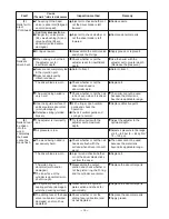
Страница 16: ...ith proper nails Nail feeding section nose feeder feed piston etc The sliding resistance of the feed piston is too great The nail guide face of the nose is abnormal deformed jagged damaged and or worn The feed spring and or feeder spring is abnormal damaged and or fatigued The feeder is abnormal damaged and or worn Remove the feed piston and examine the feed piston slide surface of the nose Apply ...

Страница 17: ...nd replace parts Adjust the height of the nail holder correctly Magazine section Pushing lever A Magazine Check whether or not a nail catches on another nail in the magazine Check whether or not a nail catches on some part of the magazine Check the nail holder for the height Correct or replace parts Output section Piston driver blade etc Air pressure is low Adjust air pressure in the range of 4 9 ...

Страница 18: ...check whether or not the piston ring the O ring and the cylinder are normal The piston ring is abnormal worn and or damaged The inner face of the cylinder is abnormal worn and or rough Adjust air pressure in the range of 4 9 8 3 bar 5 8 5 kgf cm2 70 120 psi Replace the abnormal parts 3 Nails cannot be driven into the wood completely the heads cannot be made flush The adjuster is incorrectly set Tr...

Страница 19: ...on port Check that the second claw chucks the nail shaft and feeds it Replace the abnormal parts Nose Remove the foreign matter in the feed piston chamber Body Nail feeding is incomplete The feeder is worn and the sliding section is abnormal The nail guide face of the nose and the sliding section of the feeder are abnormal deformed warped and or damaged The nail guide face of the nail guide is wor...

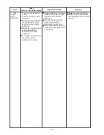
Страница 20: ... worn The O ring of valve piston B is worn The sliding face of plunger A of valve piston B is abnormal seized and or deformed Plunger A trigger A and pushing lever B are abnormal worn and or deformed The single shot continuous shot switch lever is positioned incorrectly Fault Cause The mark refers to main causes Inspection method Remedy Replace the abnormal parts Set the single shot continous shot...

Страница 21: ...art names and circled numbers refer to the Parts List Section A A Air leakage portion A Exhaust port Cause When the trigger is turned off When the trigger is turned on Abnormal Head Valve A 8 and Cylinder 16 seal surface b worn or deformed Abnormal Head Valve O ring 7 Head Valve O ring 7 or Head Valve A 8 worn deformed or broken Abnormal Exhaust Cover 4 damaged Abnormal Head Valve A 8 section a wo...

Страница 22: ...ston 12 deformed driver blade abnormal sealed surface Deformed section f of Body Ass y 20 Worn deformed broken or scratched O ring S 12 21 E Feed piston F Control valve 1 Abnormal Feed Piston 72 O ring 1AP 20 71 worn broken or scratched or the O ring sliding surface on the Nose 69 is worn deformed or scratched Abnormal Nose 69 O ring P 9 70 worn broken or scratched or the O ring sliding surface on...

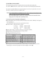
Страница 23: ... the O rings and the O ring sliding area When installing the O rings exercise care to avoid scratches and dust Lubricants required Hitachi pneumatic tool lubricant 1 oz 30 cc Oil feeder Code No 877153 4 oz 120 cc Oil feeder Code No 874042 1 quart 1 liter Can Code No 876212 Replace gasket if broken and make sure that there is no air leak after installation Exercise care to protect the valve area fr...

Страница 24: ...e removed by inserting an appropriate rod into the exhaust port As the Cylinder Packing 13 is fitted into the groove of the Cylinder 16 by a pliable rubber fit simply bend the rubber enough to slide over the side of the groove so that it can be taken out b Reassembly Reassembly can be accomplished by following the disassembly procedures in reverse However particular attention should be given to th...

Страница 25: ...o the Exhaust Cover 4 together with the Head Valve Spring 6 Prior to reassembly liberally apply grease to the head valve sliding portion A of the Exhaust Cover 4 and rib portions B and C of Head Valve A 8 and insert grease approx 0 5 g into the grooved portion of the Exhaust Cover 4 See Fig 14 Piston 12 Piston Ring 9 Fig 13 Driver blade Exhasut cover grooved portion Bumper A 11 Fig 14 Head Valve A...

Страница 26: ...First remove the Exhaust Cover 4 by following the procedure described in Item 9 2 1 above 2 Next as illustrated in Fig 16 insert a thin metal rod from the upper side of the Body Ass y 20 and push the upper surface of the Valve Piston B 63 to take out the parts that make up the control valve section with the exception of Valve Bushing B 59 and the Head Valve O ring I D 16 8 58 3 To take out Valve B...

Страница 27: ...on should be given to the following points Be very careful not to allow any foreign matter to get into the control valve section Liberally apply grease to Plunger A 66 O ring I D 1 8 67 Valve Piston B 63 O ring I D 8 8 61 and O ring S 4 62 As shown in the following illustrations assemble Valve Bushing A 68 so that its roll pin groove is aligned with the matching roll pin hole in the Body Ass y 20 ...

Страница 28: ...Tape 46 First stick one end of the Grip Tape 45 to the roll pin hole portion of the Body Ass y 20 and wrap the grip tape around the body overlapping a little 1 5 mm to 3 mm as illustrated in Fig 19 After wrapping the Grip Tape 45 securely wrap both of its ends with the Tape 46 See Fig 19 As the Grip Tape 45 and the Tape 46 cannot be removed and reapplied once they have been applied be very careful...

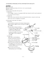
Страница 29: ...ion See Fig 20 Tools required 23 mm wide wrench Flat blade screwdriver tip thickness of 0 5 mm to 1 mm or a similar steel plate Philips screwdriver 1 Disassembly and reassembly of the cap portion a Disassembly As the Cap 48 is a single body unit equipped with M42 theads simply fit a wrench across its diameter and turn it gently to loosen and remove it b Reassembly Reassembly can be accomplished by...

Страница 30: ... 5 mm hexagon bar wrench 4 mm dia roll pin remover C type retaining ring puller Flat blade screwdriver 1 Disassembly and reassembly of the Nose 69 Pushing Lever B 38 Pushing Lever A 42 and related parts See Fig 21 a Disassembly Remove the Hex Socket Hd Bolt M6 x 20 31 and extract the Roll Pin D3 x 18 34 The Nose 69 and the pushing lever components can then be taken off Remove the Hex Socket Hd Bol...

Страница 31: ...ton 72 and the O ring 1AP 20 71 on the right side and apply grease to the groove section Apply grease to the O ring sliding portions of the Feed Piston 72 and the Nose 69 and to the O ring However as excessive grease will cause poor movement of the Feed Piston 72 be very careful not to apply too much grease Ensure that the Retaining Ring for D28 Hole 77 is properly fitted into the groove of the No...

Страница 32: ...d Bolt M4 x 10 94 Nail Guide Shaft 87 Tools required 3 mm hexagon bar wrench Flat blade screwdriver a Disassembly Using a flat blade screwdriver or similar tool remove the Shaft Ring 86 of the Nail Guide Shaft 87 and extract the Nail Guide Shaft 87 The Nail Guide 90 and the related parts can then be removed together With the 3 mm hexagon bar wrench remove the Nylock Hex Socket Hd Bolt M4 x 10 94 T...

Страница 33: ... Push Nail Stopper B 91 with a finger and confirm that they return properly Ensure there is no air leakage from each section Check that the feed piston operates properly when the machine is operated with an air pressure of 4 9 bar 5 kgf cm2 70 psi Conduct check under idle operation with the nail guide open Check that there is no idle operation or bent nails when nails are driven with an air pressu...

Страница 34: ...juster B Adjuster Spring Valve Bushing B Head Valve O ring O ring x 6 Valve Piston B Plunger Spring Plunger A Valve Bushing A Adjustment Cylinder Body and Valve Body Ass y Feed Piston O ring x 2 Feed Spring Bumper Feed Piston Cover Change Knob B Spring C Feeder Arm Feeder Spring Feeder Guide Shaft Vertical Guide Cylinder Cylinder Packing Cylinder Washer A O ring Piston Bumper Nose Magazine Ass y N...

Страница 35: ... 5 6 7 8 9 10 11 12 13 14 15 16 17 18 19 21 22 23 24 25 26 27 28 29 30 31 32 33 34 35 36 37 38 39 40 41 42 43 44 45 46 47 48 49 51 52 53 54 55 56 57 58 59 60 61 62 63 64 65 66 67 68 69 70 71 72 73 74 75 76 77 78 81 80 82 83 84 85 86 32 33 35 36 36 87 88 89 90 91 92 93 94 501 502 503 504 505 506 3 20 79 50 ...

Страница 36: ...0 885 251 BODY ASS Y 1 INCLUD 45 46 20 882 104 BODY ASS Y 1 INCLUD 45 46 FOR H V 21 875 638 O RING S 12 1 22 880 674 TRIGGER A 1 23 880 194 PUSHING LEVER GUIDE 1 24 873 093 O RING 1AP 3 1 25 880 176 ADJUSTER STOPPER 1 26 949 770 ROLL PIN D4X14 10 PCS 1 27 983 545 NEEDLE ROLLER 1 28 878 132 FEEDER ARM 1 29 878 340 FEEDER SPRING 1 30 880 433 FEEDER 1 31 949 660 HEX SOCKET HD BOLT M6X20 10 PCS 2 32 8...

Страница 37: ... 67 878 888 O RING I D 1 8 1 68 880 671 VALVE BUSHING A 1 69 880 430 NOSE 1 70 872 645 O RING P 9 1 71 944 486 O RING 1AP 20 1 72 878 579 FEED PISTON 1 73 880 445 FEED SPRING 1 74 877 711 BUMPER 1 75 880 331 FEED PISTON COVER 1 76 878 305 MAGAZINE BUSHING 1 77 939 555 RETAINING RING FOR D28 HOLE 10 PCS 1 78 877 371 NYLON NUT M5 1 79 878 183 WARNING LABEL 1 EXCEPT FOR H V 80 880 436 MAGAZINE 1 81 8...

Страница 38: ...NO DESCRIPTION REMARKS NO USED NV 50AG2 Printed in Japan 050120N 501 875 769 SAFETY GLASSES 1 502 880 444 CASE 1 502 882 105 CASE 1 FOR H V 503 877 153 PNEUMATIC TOOL LUBRICANT 30CC 1 504 943 277 HEX BAR WRENCH 3MM 1 505 944 458 HEX BAR WRENCH 4MM 1 506 944 459 HEX BAR WRENCH 5MM 1 601 881 012 SEQUENTIAL TRIP MECHANISM SET 1 ...

Страница 39: ......

Отзывы: