Chapter 2 Specifications
2 – 71
Specifications (continued from the preceding page)
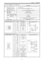
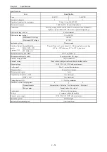
Item Specification
Pulse chain (CW/CCW) output
Clock + Direction signal
(CK/Direction) pulse output
1. Open collector output photo-coupler insulation (30 V DC at the maximum, 30
mA resistive load)
2. Line driver output photo-coupler insulation (5 V DC)
Maximum leak current
100
μ
A
Output
Maximum voltage drop at ON
0.8 V at the maximum (at output current 30 mA)
Input voltage
10.8 to 30 V DC
Input impedance
Approx. 2.2 k
Ω
Input current
10 mA (24 V DC) maximum
Minimum ON voltage
9 V
Operating
voltage
Maximum OFF voltage
3.6 V
ON
Æ
OFF
1 ms maximum
Input lag
OFF
Æ
ON
1 ms maximum
Polarity
Only encoder signal input uses the plus common inside the unit,
and other inputs do not specify polarity.
Input
Insulation system
Photo-coupler
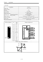
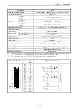
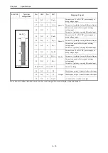
A) Specifications of Positioner connector (CN1): conforms to RS-422
Terminal configuration
No.
Signal
Signal name
Diagram of Internal circuit
1
Do -
Driver output -
2
Do +
Driver
3
Ri -
Receiver input -
4
Ri +
Receiver input +
5
5 V DC +
+ 5 V
6 0
V
GND
7 0
V
GND
8
12 V DC -
-12 V
1
8
.
.
.
.
.
.
8
7
6
5
2
1
4
3
P
o
si
tione
r
Internal
circuit
-12V
GND
5V
5V
GND
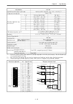
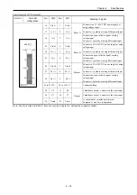
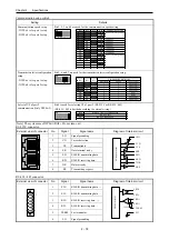
B) Specifications of I/O connector (CN2)
Terminal configuration
No.
Signal
Signal name
Diagram of Internal circuit
1
5 V DC +
2 0
V
Pulse output power
supply
3 CW
4 CCW
Open collector pulse
output
5 CW
+
6 CW
-
7 CCW
+
8 CCW
-
Line driver pulse
output
9 C
+
10 C
-
Encoder C phase
11 PS
-
12 PS
+
Encoder position
signal
13 COIN
Positioning
complete
14
PROG
Home position LS
15
+ 0.RUN
+ Overrun
16
- 0.RUN
- Overrun
17
MODE - SEL
Control mode switch
18
M – CW
Manual CW
19
M – CCW
Manual CCW
11
20
1
10
. .
. .
.
.
. .
. .
.
.
20
24 V DC +
Control power supply
Internal
circuit
5V
20
2
3, 4
1
5, 7
5V
6, 8
9, 11
10, 12
13 - 19


