Chapter 4 Installation (hardware)
4 – 9
(b) Wiring for the transistor output module
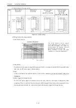
1] Flywheel diode
For inductive load, connect a flywheel diode in parallel.
2] S and C terminals
Always connect an S terminal and C (common) terminal. If the module is used without connecting these
terminals, the internal flywheel diode does not function and there is a risk that the module will
malfunction or breakdown.
3] Fuse
A fuse is inserted in the common to prevent the external wiring from burning out, but this does not protect
transistor elements. Therefore, note that these elements are destroyed when the external load is
short-circuited. Please contact us for repair if the external load short-circuits.
Also, if the fuse blows, there will be no output even if the LED lights up. (The fuse out lamp for the
module at this time as well as a CPU module error will not be displayed.)
Note: If the fuse is melted or blown, do not supply power to the module after changing the fuse without
eliminating the source of the problem. Damage escalation, smoke, etc., may otherwise result.
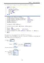
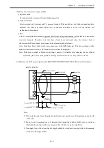
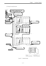
(c) Wiring for the 32/64-point output module (EH-YT32/YTP32,EH-YT64/YTP64) (Based on CE marking)
Note:
1] Wire only the signal line through the shield cable and provide class D grounding on the shield
cable side.
2] Do not wire the common line or S terminal line through the shield cable. Be sure to sire them
independently and separately from the power line, I/O lines or power supply line.
3] The supply line to the external power supply should be wired as close as possible to the common
terminal of the output module.
0
1
2
31
C
Common
terminal
Class D
grounding
Signal line
Common line
External power supply
Shield cable
+
+
EH-YT32, EH-YTP32
S
S terminal line
At using EH-YTP**
At using EH-YT**

