background image

Rebooting or shutting down a server

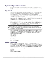
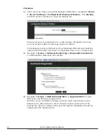
The server can be shutdown or reset if a manual reboot is necessary.

Procedure

1.

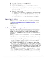
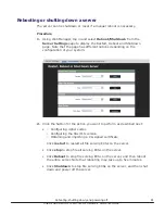
Using Web Manager, log in and select 

Reboot/Shutdown

 from the

Server Settings

 page to display the Restart, Reboot and Shutdown

page. Note that the page has different options depending on the
configuration of your system.


2.

Click the button for the action you want to perform as described next:

Configuring cipher suites

Configuring the SSL/TLS version

Obtaining and importing a CA-signed certificate

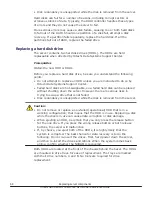
Click 

restart

 to restart all file serving EVSs on the server.

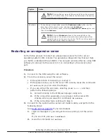
• Click 

stop

 to stop file all serving EVSs on the server.

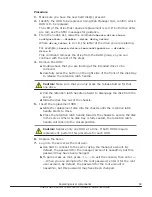
• Click 

Reboot

 to stop file serving EVSs on the server, and then reboot

the entire server. Note that rebooting may take up to five minutes.

• Click 

Shutdown

 to stop file serving EVSs on the server, and then shut

down and power off the server.

Rebooting, shutting down, and powering off

81

Hitachi NAS Platform 3080/3090 G2 Hardware Reference Guide

Содержание 3080 G2

Страница 1: ...Hitachi NAS Platform 3080 and 3090 G2 Hardware Reference Release 12 2 MK 92HNAS017 05 ...

Страница 2: ... publication When new or revised information becomes available this entire document will be updated and distributed to all registered users Some of the features described in this document might not be currently available Refer to the most recent product announcement for information about feature and product availability or contact Hitachi Data Systems Corporation at https portal hds com Notice Hit...

Страница 3: ... OpenSSL Project for use in the OpenSSL Toolkit http www openssl org Some parts of ADC use open source code from Network Appliance Inc and Traakan Inc Part of the software embedded in this product is gSOAP software Portions created by gSOAP are copyright 2001 2009 Robert A Van Engelen Genivia Inc All rights reserved The software in this product was in part provided by Genivia Inc and any express o...

Страница 4: ... regulations 24 International standards 25 Federal Communications Commission FCC 25 European Union EU Statement 26 Canadian Department of Communication Compliance Statement 26 Avis de conformité aux normes du ministère des Communications du Canada 27 Radio Protection for Germany 27 Food and Drug Administration FDA 27 Chinese RoHS Compliance Statement 27 4 System overview 30 System components 31 Se...

Страница 5: ...ent port 57 10 100 1000 Ethernet management ports 58 Ethernet cables 58 6 Replacing server components 60 Field replaceable units 61 Hot swappable components 61 Removing and replacing the front bezel 62 Bezel removal 62 Bezel replacement 62 Replacing a fan 62 Replacing the NVRAM backup battery pack 64 Checking battery pack status 64 Identifying a cluster node that requires battery replacement 65 Re...

Страница 6: ...figuration 97 Replacing a single server with an external SMU 99 Obtaining backups diagnostics firmware levels and license keys 99 Shutting down the server you are replacing 101 Configuring the replacement server 103 Finalizing and verifying the replacement server configuration 105 Replacing a node within a cluster 107 Obtaining backups diagnostics firmware levels and license keys 107 Shutting down...

Страница 7: ...7 Hitachi NAS Platform 3080 3090 G2 Hardware Reference Guide ...

Страница 8: ...92HNAS014 In PDF format this guide explains how to log in to the system provides information about accessing the NAS server cluster CLI and the SMU CLI and provides information about the documentation help and search capabilities available in the system Server and Cluster Administration Guide MK 92HNAS010 In PDF format this guide provides information about administering servers clusters and server...

Страница 9: ...using file based replication and object based replication provides information on setting up replication policies and schedules and using replication features for disaster recovery purposes Antivirus Administration Guide MK 92HNAS004 In PDF format this guide describes the supported antivirus engines provides information about how to enable them and how to configure the system to use them Backup Ad...

Страница 10: ...HNAS Deduplication Hitachi NAS Platform Best Practices for Tiered File Systems MK 92HNAS038 This document describes the Hitachi NAS Platform feature that automatically and intelligently separates data and metadata onto different Tiers of storage called Tiered File Systems TFS Hitachi NAS Platform Data Migrator to Cloud Best Practices Guide MK 92HNAS045 Data Migrator to Cloud allows files hosted on...

Страница 11: ...ms SU 12 x Network File System NFS Version 4 Feature Description MK 92HNAS056 This document describes the features of Network File System NFS Version 4 Preface 11 Hitachi NAS Platform 3080 3090 G2 Hardware Reference Guide ...

Страница 12: ...ll and configure the hardware and software and how to replace faulty components The following server models are covered 3080 and 3090 For assistance with storage arrays connected to the server refer to the Storage Subsystem Administration Guide Audience Conventions Related documentation 12 About this manual Hitachi NAS Platform 3080 3090 G2 Hardware Reference Guide ...

Страница 13: ...his bold fixed space font denotes literal items that the user enters in interactive sessions Output is shown in nonbold fixed space font and Brackets enclose optional portions of a command or directive line Ellipses indicate that a preceding element can be repeated GUI element This font denotes the names of graphical user interface GUI elements such as windows screens dialog boxes menus toolbars i...

Страница 14: ...g DEUTSCH Die folgenden Symbole werden in diesem Handbuch zur Anzeige von Sicherheitshinweisen verwendet Lesen Sie die so gekennzeichneten Informationen durch um die erforderlichen Maßnahmen zu ergreifen Anmerkung Mit einer Anmerkung wird auf Informationen verwiesen die Sie beachten sollten VORSICHT Das Wort Vorsicht weist auf mögliche Schäden für Daten oder Ihre Ausrüstung hin Sie sollten erst da...

Страница 15: ...e Operazioni preliminari ITALIANO Le seguenti icone vengono utilizzate nella guida a scopo cautelativo Prima di procedere Vi viene richiesta un attenta lettura di tutte le procedure contrassegnate dalle suddette icone affinché vengano applicate correttamente Suggerimento Suggerimento fornisce indicazioni supplementari comunque utili allo scopo ATTENZIONE Attenzione indica il potenziale danneggiame...

Страница 16: ...ste um possível risco para a segurança pessoal Ennen kuin aloitat SUOMI Seuraavilla kuvakkeilla kiinnitetään tässä oppaassa huomiota turvallisuusseikkoihin Näillä kuvakkeilla merkityt menettelytavat tulee lukea ja ymmärtää ennen jatkamista Huomautus Huomautus sisältää tietoja jotka tulee ottaa huomioon VAROITUS Varoitus varoittaa tietojen tai laitteiden vahingoittumisen mahdollisuudesta Tällä merk...

Страница 17: ...ing file systems and enabling and configuring file services file service protocols Data Migrator Administration Guide MK 92HNAS005 In PDF format this guide provides information about the Data Migrator feature including how to set up migration policies and schedules Storage Subsystem Administration Guide MK 92HNAS012 In PDF format this guide provides information about managing the supported storage...

Страница 18: ...tform 3080 and 3090 G2 Hardware Reference MK 92HNAS017 Provides an overview of the first generation server hardware describes how to resolve any problems and replace potentially faulty parts Hitachi NAS Platform Series 4000 Hardware Reference MK 92HNAS030 Provides an overview of the Hitachi NAS Platform Series 4000 server hardware describes how to resolve any problems and how to replace potentiall...

Страница 19: ...About this manual 19 Hitachi NAS Platform 3080 3090 G2 Hardware Reference Guide ...

Страница 20: ...ty guidelines to follow when working with the equipment Electrostatic discharge precautions Safety and handling precautions Electrical precautions Data protection precautions 20 Safety information Hitachi NAS Platform 3080 3090 G2 Hardware Reference Guide ...

Страница 21: ...ng all storage enclosures from the bottom to the top Do not remove more than one unit from the rack at a time To help prevent serious injuries load the components in the storage cabinet in the prescribed order 1 If present install the rack stabilizer plate to the front of the system cabinet 2 Load the Fibre Channel FC switches in the storage cabinet at the positions recommended in the System Insta...

Страница 22: ...nge 100 240Vac 6A max 50 60Hz Caution Turn off all power supplies or remove all power cords before undertaking servicing of the system Unplug a system component if it needs to be moved or if it is damaged Note For additional data protection Hitachi recommends that you use an external UPS to power the server Also each of the redundant power supplies in the server and in the storage subsystems shoul...

Страница 23: ...et All storage enclosures are fitted with optical SFP transceivers The transceivers that are approved for use with supported storage enclosures vary depending on the unit The transceivers qualified for older systems might not be approved for use with the most current storage systems To ensure proper operation of the server and the storage subsystems use only the approved replacement parts for each...

Страница 24: ...e that regulatory compliance requirements are met International standards Federal Communications Commission FCC European Union EU Statement Canadian Department of Communication Compliance Statement Radio Protection for Germany Food and Drug Administration FDA Chinese RoHS Compliance Statement 24 Mandatory regulations Hitachi NAS Platform 3080 3090 G2 Hardware Reference Guide ...

Страница 25: ...cation by CoC Federal Communications Commission FCC This equipment has been tested and found to comply with the limits for a Class A digital device pursuant to Part 15 of the FCC Rules These limits are designed to provide reasonable protection against harmful interference when the equipment is operated in a commercial environment This equipment generates uses and can radiate radio frequency energy...

Страница 26: ...ion in the use of Certain Hazardous Substances in Electrical and Electronic Equipment RoHS This product is 6 6 fully compliant The manufacturer cannot accept responsibility for any failure to satisfy the protection requirements resulting from a non recommended modification of the product This product has been tested and found to comply with the limits for Class A Information Technology Equipment a...

Страница 27: ...el brouilleur du Canada Radio Protection for Germany Dieses Gerät erfüllt die Bedingungen der EN 55022 Klasse A Food and Drug Administration FDA The product complies with FDA 21 CFR 1040 10 and 1040 11 regulations which govern the safe use of lasers Chinese RoHS Compliance Statement Mandatory regulations 27 Hitachi NAS Platform 3080 3090 G2 Hardware Reference Guide ...

Страница 28: ...28 Mandatory regulations Hitachi NAS Platform 3080 3090 G2 Hardware Reference Guide ...

Страница 29: ...Mandatory regulations 29 Hitachi NAS Platform 3080 3090 G2 Hardware Reference Guide ...

Страница 30: ...hi NAS Platform server system for the following models Hitachi NAS Platform Model 3080 Hitachi NAS Platform Model 3090 System components Server specifications Attaching a rack stabilizer plate 30 System overview Hitachi NAS Platform 3080 3090 G2 Hardware Reference Guide ...

Страница 31: ...tion and monitoring tools It supports data migration and replication and acts as a quorum device in a cluster configuration Although integral to the system the SMU does not move data between the network client and the servers In a single server configuration typically an embedded SMU manages the system In clustered systems and some single node systems an external SMU provides the management functi...

Страница 32: ...ifications The following specifications are for the server Except for the power and cooling values these specifications do not reflect differences among models they are the maximum for all server models For more detailed specifications of a particular model or configuration contact your representative Physical Weight 25 kg 55 lb Height 132 mm 5 2 in Depth including handles and bezel 685 mm 27 in W...

Страница 33: ...erature change per hour transit 20 C 36 F Humidity Operational 20 80 Storage 10 90 Transit 5 95 Noise A weighted Sound Power Level Lwa db re 1pW Typical 71 Max 81 Shock and vibration Optional random vibration 10 to 350 Hz 0 18 Grms Non operational sinusoidal vibration 60 to 350 Hz 1g Non operational shock 3g 11ms half sine Packaged transport specification Drops from 356mm and 508mm as per ASTM D52...

Страница 34: ...tabilizer contains two holes for securing it to the ground Use suitable screws to secure the stabilizer Note Attach the stabilizer plate to the rack before loading the cabinet Procedure 1 Place the stabilizer plate up against the bottom of the front side of the cabinet 2 Align the holes from the stabilizer plate to the holes on the bottom of the cabinet 3 Place the screws in the holes and secure t...

Страница 35: ...System overview 35 Hitachi NAS Platform 3080 3090 G2 Hardware Reference Guide ...

Страница 36: ... a cluster configuration see the Hitachi NAS Platform and Hitachi Unified Storage File Module System Installation Guide The Hitachi NAS Platform server chassis consists of A removable fascia MMB Mercury Motherboard MFB Mercury FPGA Board Two hot swappable fan assemblies Dual power supplies NVRAM backup battery pack Dual hot swappable 2 5 inch disk drives Two PCI slots two PCI e x16 slots and two P...

Страница 37: ... Server rear panel Rear panel server LED and button locations Management interfaces Ethernet cables Hitachi NAS Platform server components 37 Hitachi NAS Platform 3080 3090 G2 Hardware Reference Guide ...

Страница 38: ... the server in a built in installation unless proper ventilation is provided Do not operate the server in a cabinet whose internal ambient temperature exceeds 35º C 95º F Server front panel The front of the server features a removable bezel that shields the front facing server components Once the bezel is removed the front facing components on the server chassis are visible Figure 5 1 Server front...

Страница 39: ... LED 9 Server status LED 10 NVRAM battery backup pack status LED 11 Fan 1 status LED 12 Fan 2 status LED LED status indicators The LEDs light emitting diodes on the front of the chassis indicate the overall status of the server as well as the status of some of the individual components The NVRAM backup battery pack each of the hard disk drives and each of the fan assemblies has a status LED Hitach...

Страница 40: ...operation with a single server or an active cluster node in operation Slow flash once every three seconds The system has been shut down Medium flash once every 8 seconds The server is available to host file services but is not currently doing so Also if no EVS is configured or all EVSs are running on the other node in a cluster Fast flash five flashes per second The server is rebooting Off The ser...

Страница 41: ...ation Off Normal operation Table 5 6 Fan status LEDs LEDs Meaning Red Fan has failed fan speed is out of acceptable range or fan speed is not being reported This LED will be on if the corresponding fan has been removed When on this LED indicates a failure and that the fan is not operating correctly Replace the fan as soon as possible Off Normal operation Table 5 7 Hard disk activity and status LED...

Страница 42: ...NVRAM backup battery pack front view Figure 5 5 NVRAM battery backup pack location behind bezel Battery pack characteristics Each server contains a single battery module The module contains dual redundancy inside The battery pack uses NiMH technology A battery pack has a two year operational life A timer starts when a server is booted for the first time and the timer is manually restarted when a r...

Страница 43: ...tdown a power outage that lasts longer than 72 hours or if a server is left unpowered for a long period of time If the battery pack is fully discharged The battery pack may permanently lose some long term capacity Assuming a battery conditioning cycle is not started a fully discharged battery pack takes up to 3 hours before it is fully charged If a battery conditioning cycle is started a fully dis...

Страница 44: ...ta storage that is available to the server Hard disks are located behind the bezel on the left side of the chassis Note Failed hard disks are hot swappable so a failed hard disk can be replaced without shutting down the server However there are serious risks in trying to swap a drive that is not failed Figure 5 6 Hard disk drives status and activity status LEDs models 3080 and 3090 Item Descriptio...

Страница 45: ... cabinet with associated components required to make up a storage system The storage system administrator is responsible for ensuring that the ambient temperature within the rack does not exceed the 35 C operating limit The server continues to operate following the failure of a single fan and during the temporary removal of a fan for replacement Replace a failed fan as soon as possible Caution If ...

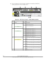
Страница 46: ...nge or fan speed is not being reported This LED will be on if the corresponding fan has been removed When on this LED indicates a failure and that the fan is not operating correctly Replace the fan as soon as possible Off Normal operation Server rear panel The rear panel of the server features numerous ports connectors switches and LEDs 46 Hitachi NAS Platform server components Hitachi NAS Platfor...

Страница 47: ...uration Connect to 10 GbE switch 2 10 GbE network ports 2 Connection to external 10 Gbps Ethernet data network 3 Gigabit Ethernet network ports 6 Connection to external Ethernet data network 4 10 100 Ethernet port 5 Connection to private management network 5 Storage or FC switch 4 Connection to disk arrays or where present to the FC switches 6 n a 3 Status LEDs NVRAM power and server and Power and...

Страница 48: ... button locations The rear panel of the server contains three 3 status LEDs that indicate server status and two 2 buttons that are used to power up and reset the server Figure 5 9 Rear panel server LEDs and buttons Item Meaning 1 NVRAM battery backup status LED 2 Power status symbol and LED 3 Server status LED 4 Reset button 5 Power button Rear panel LED state descriptions The NVRAM power and serv...

Страница 49: ...other node in a cluster Fast flash five flashes per second The server is rebooting Off The server is not powered up Table 5 13 Server status LED amber LEDs Meaning Amber Critical failure and the server is not operational Slow flash once every three seconds System shutdown has failed Flashes once every three seconds Medium flash once every 8 seconds The server needs attention and a non critical fai...

Страница 50: ... may produce a dump automatically Pressing the reset button for more than five seconds when the server is not powered up disables the NVRAM battery pack which may be necessary prior to shipping if an incomplete shutdown occurred See Powering down the server for shipment or storage on page 85 for more information Caution If the server is non responsive see Restarting an unresponsive server on page ...

Страница 51: ...d when joining a server to the private management network you must connect from one of these ports to the management interface port on the server The 10 100 ports operate at speeds of up to 100 megabits per second and require the use of a standard RJ45 cable connector The 10 100 Private Management Ethernet Network ports are labeled as shown next Figure 5 11 10 100 Private Management Network Ethern...

Страница 52: ...two indicator LEDs one green and one amber These LEDs provide link status and network activity status information as follows Status Activity Per Port Meaning Status Green On not flashing 1 Gbps link present Green Flashing 1 Gbps link standby in a redundant configuration Green Off No link Activity Amber Flashing Network activity Amber Off No network activity 10 GbE Ports Figure 5 13 NAS Platform 10...

Страница 53: ...net GbE customer data network ports are used to connect the server or cluster node to the customer s data network also called the public data network These ports may be aggregated into a 1 2 3 or 4 aggregated port See the Network Administration Guide for more information on creating aggregations The 10 GbE ports operate at speeds of ten 10 gigabits per second The 10 GbE ports use enhanced small fo...

Страница 54: ...r The server monitors the operational status of the power supply modules so that the management interfaces can indicate the physical location of the failed PSU LED indicators provide PSU status information for the state of the PSU Figure 5 16 Power supply unit details Item Description 1 PSU fan exhaust 2 Power cord connector 3 PSU retention latch 4 PSU handle 5 DC power status LED 6 PSU status LED...

Страница 55: ...ower supply unit on page 71 for more information on replacing a PSU Table 5 16 AC power status LED green amber Status Meaning Green Receiving AC power and operating normally Off Not receiving AC power check mains and power cable connections Mains power connections are an IEC inlet in each power supply Each PSU is only powered from its mains inlet Two power feeds are required for the system PSU uni...

Страница 56: ...hese ports are used to connect USB devices to the server during some operations Valid USB devices include Flash drives External hard drives USB keyboards Valid operations include Management Install Upgrade Update Repair Note The USB ports should not be used without guidance from Hitachi Data Systems Support Center Management interfaces The server panel features two types of physical management por...

Страница 57: ...face for the server The primary management interface to the server is through the Web Manager GUI or through server s command line interface CLI which can be accessed through the network Any VT100 terminal emulation interface can be used to access to the CLI so that you can perform management or configuration functions Connect the terminal to the serial port on the rear panel of the server then se...

Страница 58: ... connector Once connected each GE port has two indicator LEDs one on the top left and the second on the top right of the port These LEDs provide link status and network activity status information as described in the next table Ethernet cables The HNAS 3080 and 3090 models require CAT6 cables that fully comply with the CAT6 SF UTP standard for the 1000Base T GE Ethernet network ports Always use CA...

Страница 59: ...Hitachi NAS Platform server components 59 Hitachi NAS Platform 3080 3090 G2 Hardware Reference Guide ...

Страница 60: ...cribes which components are hot swappable Field replaceable units Hot swappable components Removing and replacing the front bezel Replacing a fan Replacing the NVRAM backup battery pack Replacing a hard disk Replacing a power supply unit Replacing an FPGA board as a FRU 60 Replacing server components Hitachi NAS Platform 3080 3090 G2 Hardware Reference Guide ...

Страница 61: ...repair MMBs are not FRUs and typically MFBs are also not FRUs However an MFB may be replaced under certain specific circumstances Contact Hitachi Data Systems Support Center to determine whether your MFB can be replaced as a FRU Some components are also hot swappable See Hot swappable components on page 61 for details Hot swappable components Some components are hot swappable Such components can b...

Страница 62: ...ssis Figure 6 1 Server front bezel with grasping areas Procedure 1 To remove the bezel grasp the front of the bezel by the grasping areas 2 Gently pull the bezel straight out away from the server Bezel replacement Procedure 1 Place the bezel on the server making sure that the bezel fits inside the outer edges of the chassis and that the retention posts and status LEDs are aligned 2 Using the solid...

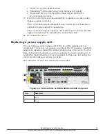
Страница 63: ...status LED for fan 1 the left side fan and number 2 indicates the status LED for fan 2 the right side fan Figure 6 2 Fan status LEDs Item Description 1 Fan 1 status LED 2 Fan 2 status LED 3 Remove the faulty fan by loosening the thumbscrews turning them counter clockwise until they are loose then pulling the fan unit straight out of the chassis The fan lead connector disengages automatically as yo...

Страница 64: ...ng down the server or migrating all of the EVSs to the other node is not required However during the replacement procedure there will be a period of time when the NVRAM contents are not backed up by the battery pack If a power failure occurs during this period the NVRAM contents may be lost Checking battery pack status The battery pack status LED indicates the status of the server s NVRAM battery ...

Страница 65: ...Identifying a cluster node that requires battery replacement If you have warnings or battery related events in the Event Log of a cluster you can identify the cluster node requiring battery replacement using the following procedure Procedure 1 Access the server command line interface For information about how to access the server command line interface refer to the Hitachi NAS Platform System Acce...

Страница 66: ...VRAM battery module removal components models 3080 and 3090 Item Description 1 Thumbscrew that holds the battery pack in place 2 Handle for moving the battery pack forward and backward in the chassis Procedure 1 Remove the bezel cover from the front of the server for access to the batteries 2 Loosen the thumbscrew to the right of the battery pack module cover by turning it counter clockwise 3 Usin...

Страница 67: ...cess Use the process described in this section to help ensure that all partitions are recovered before proceeding with any further disk recovery or replacement procedures Before you consider replacing a hard disk drive be sure you understand the following points Do not attempt to replace an HDD unless you are instructed to do so by Hitachi Data Systems Support Center Failed hard disks are hot swap...

Страница 68: ... without shutting down the server However there are serious risks in trying to swap a drive that is not failed Disk redundancy is unsupported while the disk is removed from the server Caution Do not remove or replace a non failed operational HDD that is in a working configuration that means that the HDD is in use Replacing a disk while the disk is in use can cause data corruption or disk damage Wh...

Страница 69: ...e retention latch handle outward to disengage the disk from the server d Slide the disk tray out of the chassis 5 Insert the replacement HDD a Slide the replacement disk into the chassis until the retention latch handle starts to close b Press the retention latch handle towards the chassis to secure the disk in the server When the disk tray is fully seated the retention latch handle will click int...

Страница 70: ...ed with the older disk Procedure 1 Wait until the LEDs on the front of the server slow to indicate normal activity 2 Use a serial cable connected to the serial console port of the server to access the Bali console 3 Once you have successfully logged in select the server or node that has the disks you want to synchronize 4 Run the chassis drive status command and look at the values in the Status an...

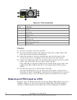
Страница 71: ...8 Shut down the server Replacing a power supply unit You can replace a power supply unit PSU as a hot swappable server component The server can operate on a single PSU if necessary making it possible to replace a failed PSU without shutting down the server If a PSU fails it should be replaced as quickly as possible because operating on a single PSU means that there is no redundancy in that area in...

Страница 72: ...s fully inserted If the PSU that is not being replaced is receiving mains power when the replacement PSU is fitted the fan on the replacement PSU becomes active 5 Connect the power cord to the back of the PSU The PSU should start as soon as the power connection is made If the PSU does not start immediately make sure the mains power circuit is live and that the other end of the power cable is conne...

Страница 73: ...must be shut down and removed from the rack before the replacement procedure can be started After the MFB has been replaced the server can be put back into the rack reattached and restarted Procedure 1 Using Web Manager log in and select Reboot Shutdown from the Server Settings page to display the Restart Reboot and Shutdown page Note that the page has different options depending on the configurat...

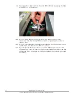
Страница 74: ...7 Using the 1 Phillips screwdriver remove and set aside the two 2 MFB retaining screws 74 Replacing server components Hitachi NAS Platform 3080 3090 G2 Hardware Reference Guide ...

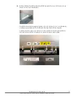
Страница 75: ...oximately 2 to 2 5 inches 5 to 7 centimeters creating a gap between the MFB and the top front of the chassis Looking into the gap you will see six 6 cables connecting the MFB to the rest of the server A cable tie is used to secure each cable Replacing server components 75 Hitachi NAS Platform 3080 3090 G2 Hardware Reference Guide ...

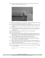
Страница 76: ...iner tabs 11 Once all internal cables have been disconnected remove the MFB Turn it upside down and place it on a flat work surface 12 Open the box that contains the replacement MFB module Remove the module and orient it so that the module cover labels face down This will protect the sheet metal tabs on the bottom side of the module see next illustration 76 Replacing server components Hitachi NAS ...

Страница 77: ...slides under the front half of the server cover Apply adequate pressure to force the woven EMI gasket under the front cover and to align the MFB front retainer holes with the mating threads on the base server sheet metal 20 Secure the MFB to the chassis base using the screws that were previously removed Carefully secure the screws using the 1 Phillips driver Avoid over tightening the fasteners 21 ...

Страница 78: ... Place the replaced module in the shielding bag and insert it in the original packaging for return to the supplier 78 Replacing server components Hitachi NAS Platform 3080 3090 G2 Hardware Reference Guide ...

Страница 79: ...Replacing server components 79 Hitachi NAS Platform 3080 3090 G2 Hardware Reference Guide ...

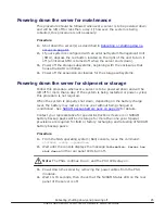
Страница 80: ...t server software licenses Rebooting or shutting down a server Rebooting or shutting down a cluster Restarting an unresponsive server Powering down the server for maintenance Powering down the server for shipment or storage Powering on the server or cluster Recovering from power standby 80 Rebooting shutting down and powering off Hitachi NAS Platform 3080 3090 G2 Hardware Reference Guide ...

Страница 81: ...rform as described next Configuring cipher suites Configuring the SSL TLS version Obtaining and importing a CA signed certificate Click restart to restart all file serving EVSs on the server Click stop to stop file all serving EVSs on the server Click Reboot to stop file serving EVSs on the server and then reboot the entire server Note that rebooting may take up to five minutes Click Shutdown to s...

Страница 82: ...tart To restart all file serving EVSs on all cluster nodes select the Restart on all nodes option and then click restart Stop File Serving To stop all file serving EVSs on a single node select the Stop file serving on node option use the drop down list to select a node and then click stop To stop all file serving EVSs on all cluster nodes select the Stop file serving on all nodes option and then c...

Страница 83: ...blems You can gain access either by using SSH software to connect to the server s CLI or connecting to the server serial port Procedure 1 Connect to the SMU using the ssh software 2 From the siconsole select the server If the system fails to respond go to step 3 If the system takes you to the server OS console issue the command bt active so you can view the display If you are still at the siconsol...

Страница 84: ... process 5 Check the green LED on the front panel of the server for the server status Table 7 1 Server status model HNAS 3080 and 3090 Server status LED Meaning Amber Critical failure and server is not operational Slow green flash every three seconds System has been shut down and you can remove the power Medium green flash every 8 seconds Server needs attention and a non critical failure has been ...

Страница 85: ...tem is being restarted or power cycled this procedure is not required When the system is properly shut down depending on the battery charge level the battery may last up to one year without being charged or conditioned See NVRAM backup battery pack on page 42 for details Contact your representative for special instructions if servers or NVRAM battery backup packs will be in storage for more than o...

Страница 86: ...e that the disk drives in some storage enclosures will not spin up until commanded to do so by the RAID controller so the LEDs may continue to blink until after the RAID controller enclosure has sent those commands and the drives have spun up 3 For a cluster configuration or when using an external System Management Unit SMU start the SMU by depressing the red button located on the right of the uni...

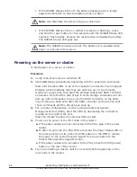
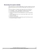
Страница 87: ...owerdown command has been issued The PWR button was pressed when the server is running The server has shut down automatically due to an over temperature condition You can restore the server to its normal power state by either of the following methods Pressing the PWR button Remove the power cables from both PSUs wait for 10 seconds then reconnect the cables to the PSUs Rebooting shutting down and ...

Страница 88: ...anagement Two node cluster using an external SMU for management replacing only one node Two node cluster using an external SMU for management replacing both nodes Important This document does not treat migration scenarios between different configurations at the time of replacement Replacement procedure overview Replacing a single server with an embedded SMU Replacing a single server with an extern...

Страница 89: ...when replacing one server in a cluster Note Replacement servers are shipped without an embedded system management unit SMU so you must have a SMU installed before you can connect to a standalone server You can use a KVM keyboard video and mouse device or a serial cable to connect to the serial port Bring both devices with you just in case both are needed when the unit arrives If you connect to the...

Страница 90: ...ally be replaced with a permanent key This is required for all field scenarios except when replacing a single node in a cluster Note If the scenario is a single node or all cluster node replacement use the span allow access command to attach the storage when the MAC ID changes Previous backups A system backup preserves two critical components of information SMU configuration Server configuration T...

Страница 91: ...necessary If this circumstance is encountered call the support organization for a copy of the system s latest diagnostics files If available these files can be used as a guide in reestablishing the system manually The data and file systems will remain intact independent of the replacement and without a backup Note Replacement servers are shipped without an embedded system management unit SMU so yo...

Страница 92: ...re both the SMU and server configuration files in one complete set 2 Navigate to Home Status Monitoring Diagnostics download to download the diagnostic test results 3 Navigate to Home SMU Administration Upgrade SMU to verify SMU type and firmware release level Both the server and SMU firmware versions must match those on the failed server otherwise the server cannot properly restore from the backu...

Страница 93: ...anel LEDs turn off The PSU and server fans continue to run until you remove the power cables from the PSU module See the appropriate system component section for more information Note This specific powerdown command prepares the system for both shipping and potential long term post replacement storage 2 Unplug the power cords from the power supplies 3 Wait approximately 15 seconds and then confirm...

Страница 94: ...work port 3 Gigabit Ethernet network port 4 Gigabit Ethernet network port 5 Gigabit Ethernet network port 6 Gigabit Ethernet network port 3 1 10 100 Private management network Ethernet port 2 10 100 Private management network Ethernet port 3 10 100 Private management network Ethernet port 4 10 100 Private management network Ethernet port 5 10 100 Private management network Ethernet port 4 1 Storag...

Страница 95: ...ll it on the new server 10 Insert the new server into the rack and connect the power cords to the power supplies Note Do not make any other cable connections at this time Configuring the replacement server Prerequisites Obtain the necessary IP addresses to be used for the replacement server Servers shipped from the factory have not yet had the nas preconfig script run on them so a replacement serv...

Страница 96: ...oot default password nasadmin and enter ssc localhost to access the BALI level command prompt 7 Enter evs list to obtain the IP configuration for the server 8 Using a supported browser launch the Web Manager SMU GUI using either of the IP addresses acquired from the EVS list output 9 Click Yes and log in as admin default password nasadmin 10 Verify and if necessary convert the new server to the mo...

Страница 97: ...nel FC link speed varies according to the server model Use the appropriate speed for your model Model Fibre Channel link speed HNAS 3080 and 3090 4 Gbps On the replacement server Note The following steps show the FC link speed as 8 Gbps as an example Procedure 1 Navigate to Home Server Settings License Keys to load the license keys 2 Remove the previous license keys in the backup file and add the ...

Страница 98: ...with the new WWPN if you are using WWN based zoning If you are using port based zoning the no modifications are necessary for the switches configurations 6 Open Storage Navigator and reconfigure LUN mapping and host group on the storage system that is dedicated to the server with the new WWPNs Perform this step for every affected server port 7 If the server does not recognize the system drives ent...

Страница 99: ...vice restarts client access and that customer expectations are all in place Features such as replication and data migration should all be confirmed as working and all file systems and storage pools should be online Replacing a single server with an external SMU Note that if it is a single server with an external SMU that is nonfunctioning and does not have a recent backup saved off platform then a...

Страница 100: ...set 2 Navigate to Home Status Monitoring Diagnostics download to download the diagnostic test results 3 Navigate to Home Server Settings Firmware Package Management to verify the existing server SU firmware release level The server firmware version must match the failed server otherwise the server cannot properly restore from the backup file See the release notes and system installation guide for ...

Страница 101: ...ove the power cables from the PSU module See the appropriate system component section for more information Note This specific powerdown command prepares the system for both shipping and potential long term post replacement storage 2 Unplug the power cords from the power supplies 3 Wait approximately 15 seconds and then confirm the NVRAM status LED is off If the LED is flashing or fixed press and h...

Страница 102: ...ork port 3 Gigabit Ethernet network port 4 Gigabit Ethernet network port 5 Gigabit Ethernet network port 6 Gigabit Ethernet network port 3 1 10 100 Private management network Ethernet port 2 10 100 Private management network Ethernet port 3 10 100 Private management network Ethernet port 4 10 100 Private management network Ethernet port 5 10 100 Private management network Ethernet port 4 1 Storage...

Страница 103: ...l it on the new server 10 Insert the new server into the rack and connect the power cords to the power supplies Note Do not make any other cable connections at this time Configuring the replacement server Prerequisites Obtain the necessary IP addresses to be used for the replacement server Servers shipped from the factory have not yet had the nas preconfig script run on them so a replacement serve...

Страница 104: ...115 200 b s 8 data bits 1 stop bit No parity No flow control VT100 emulation 6 Log in as root default password nasadmin and enter ssc localhost to access the BALI level command prompt 7 Enter evs list to obtain the IP configuration for the server 8 Using a supported browser launch the Web Manager SMU GUI using either of the IP addresses acquired from the EVS list output 9 Click Yes to proceed past...

Страница 105: ...erver Settings License Keys to load the license keys 17 Remove the previous license keys and add the new keys Finalizing and verifying the replacement server configuration The Fibre Channel FC link speed varies according to the server model Use the appropriate speed for your model Model Fibre Channel link speed HNAS 3080 and 3090 4 Gbps On the replacement server Note The following steps show the F...

Страница 106: ...fc link speed FC 1 4 Gbps FC 2 4 Gbps FC 3 4 Gbps FC 4 4 Gbps 4 Use the fc link type command to configure the server in fabric N or loop NL mode 5 Modify zoning and switches with the new WWPN if you are using WWN based zoning If you are using port based zoning the no modifications are necessary for the switches configurations 6 Open Storage Navigator and reconfigure LUN mapping and host group on t...

Страница 107: ...o capture the revised configuration and then download another diagnostic to support Permanent license keys for the replacement server are normally provided within 7 days If the server is not operating normally for any reason contact support for assistance 17 Confirm all final settings IP addresses customer contact information service restarts client access and that customer expectations are all in...

Страница 108: ... both the SMU and server configuration files in one complete set 2 Navigate to Home Status Monitoring Diagnostics Download to download the diagnostic test results 3 Navigate to Home Server Settings Firmware Package Management to verify the existing server SU firmware release level The new server firmware version must match the failed server otherwise the server cannot properly restore from the bac...

Страница 109: ...until you remove the power cables from the PSU module See the appropriate system component section for more information Note This specific powerdown command prepares the system for both shipping and potential long term post replacement storage 2 Unplug the power cords from the power supplies 3 Wait approximately 15 seconds and then confirm the NVRAM status LED is off If the LED is flashing or fixe...

Страница 110: ...ork port 3 Gigabit Ethernet network port 4 Gigabit Ethernet network port 5 Gigabit Ethernet network port 6 Gigabit Ethernet network port 3 1 10 100 Private management network Ethernet port 2 10 100 Private management network Ethernet port 3 10 100 Private management network Ethernet port 4 10 100 Private management network Ethernet port 5 10 100 Private management network Ethernet port 4 1 Storage...

Страница 111: ...erver and install it on the new server 10 Insert the new server into the rack and connect the power cords to the power supplies Note Do not make any other cable connections at this time Configuring the replacement server Prerequisites Obtain the necessary IP addresses to be used for the replacement server Servers shipped from the factory have not yet had the nas preconfig script run on them so a r...

Страница 112: ...ing a supported browser launch the Web Manager SMU GUI using either of the IP addresses acquired from the EVS list output 9 Click Yes to proceed past the Security Alert and log in as admin default password nasadmin 10 Verify and if necessary convert the new server to the model profile required This step requires a separate process training and equipment Contact support if the incorrect model arriv...

Страница 113: ...e to reboot and join the cluster successfully 17 Enter smu uninstall to uninstall the embedded SMU Finalizing and verifying the server configuration On the new server Procedure 1 Navigate to Home Status Monitoring System Monitor to verify the server status If the server is operating normally and is not displaying any alarm conditions run a backup to capture the revised configuration and Server rep...

Страница 114: ...vided within 15 days If the server is not operating normally for any reason contact support for assistance 2 Navigate to Home Server Settings Cluster Configuration to verify the cluster configuration status 114 Server replacement procedures Hitachi NAS Platform 3080 3090 G2 Hardware Reference Guide ...

Страница 115: ...grate assign it to the preferred node and then click migrate 4 To set the preferred node for any remaining EVSs navigate to Home Server Settings EVS Management EVS Details Server replacement procedures 115 Hitachi NAS Platform 3080 3090 G2 Hardware Reference Guide ...

Страница 116: ...files if available to be used as a guide in reestablishing the system manually The data and file systems will remain intact independent of the replacement and without a backup Important Set expectations up front with the customer that this will delay time to recovery and that some aspects of the systems configuration might never be recovered Obtaining backups diagnostics firmware levels and licens...

Страница 117: ...ware Package Management to verify the existing server SU firmware release level The new server firmware version must match the failed server otherwise the server cannot properly restore from the backup file See the release notes and the System Installation Guide for release specific requirements 4 Navigate to Home Server Settings IP Addresses to obtain Server replacement procedures 117 Hitachi NAS...

Страница 118: ...nue to run until you remove the power cables from the PSU module See the appropriate system component section for more information Note This specific powerdown command prepares the system for both shipping and potential long term post replacement storage 2 Unplug the power cords from the power supplies 3 Wait approximately 15 seconds and then confirm the NVRAM status LED is off If the LED is flash...

Страница 119: ...Gigabit Ethernet network port 4 Gigabit Ethernet network port 5 Gigabit Ethernet network port 6 Gigabit Ethernet network port 3 1 10 100 Private management network Ethernet port 2 10 100 Private management network Ethernet port 3 10 100 Private management network Ethernet port 4 10 100 Private management network Ethernet port 5 10 100 Private management network Ethernet port 4 1 Storage or FC swit...

Страница 120: ...er into the rack and connect the power cords to the power supplies Note Do not make any other cable connections at this time Configuring the replacement servers Prerequisites Obtain the necessary IP addresses to be used for the replacement server Servers shipped from the factory have not yet had the nas preconfig script run on them so a replacement server will not have any IP addresses pre configu...

Страница 121: ...from the EVS list output 9 Click Yes to proceed past Security Alert and log in as admin default password nasadmin 10 Verify and if necessary convert the new server to the model profile required This step requires a separate process training and equipment Contact support if the incorrect model arrives for replacement 11 Navigate to Home Server Settings Firmware Package Management to verify and if n...

Страница 122: ...zing and verifying the system configuration On the new server Procedure 1 Navigate to Home Status Monitoring System Monitor to verify the server status If the server is operating normally and is not displaying any alarm conditions run a backup to capture the revised configuration and then download another diagnostic to support Permanent license keys for the new server will be provided within 15 da...

Страница 123: ...ient access and that customer expectations are all in place Features such as replication and data migration should all be confirmed as working and all file systems and storage pools should be online Server replacement procedures 123 Hitachi NAS Platform 3080 3090 G2 Hardware Reference Guide ...

Страница 124: ...base system and MFB have been replaced by whole unit servers SX325148 HNAS 3080 3090 Server HDS Includes fans and HDDs Does not include PSUs battery rails or bezel RoHS 2013 RoHS 2013 spares are required for EMEA units start with a S N starting with M2SEKW13 or higher SX325097 MK1 Battery Module each SX325098 Fan Tray ea Fan ID 3 Can also use SX325116 SX325099 Hard Disk ea 500GB System Management ...

Страница 125: ...or more nodes 224 5880 Dell PowerConnect 2824 Switch 24 Ports GigE Can use part number 222 2257 XBR VDX6730 16 R Brocade VDX 6730 10GbE Switch 16 Ports SFP AC Port Side Exhaust AF XBR 250WPSAC R Brocade VDX 6730 250W AC PS fan Port Side Exhaust XBR VDX6730 16 F Brocade VDX 6730 10GbE Switch 16 Ports SFP AC Non Port Side Exhaust AF XBR 250WPSAC F Brocade VDX 6730 250W AC PS fan Non Port Side Exhaus...

Страница 126: ...es HD 10G SFPP SR 10GBASE SR SFP optic LC target range 300m over MMF This SFP is used in the TurboIron switch part number HD TI 24X AC SX350004 SFP 1000BaseT Copper Manufacturer part number is FCMJ 8521 3 SX350000 SFP Multi Mode Fiber 2 Gbps Manufacturer part number is FTRJ8519P1BNL SX350010 SFP Multi Mode Fiber 4 Gbps Manufacturer part number is FTLF8524P2BNV SX350011 XFP 10G 850NM 1 Pk for Clust...

Страница 127: ...Parts list for 3080 3090 G2 servers 127 Hitachi NAS Platform 3080 3090 G2 Hardware Reference Guide ...

Страница 128: ...Hitachi NAS Platform 3080 3090 G2 Hardware Reference Guide ...

Страница 129: ... Street Santa Clara California 95050 2639 U S A www hds com Regional Contact Information Americas 1 408 970 1000 info hds com Europe Middle East and Africa 44 0 1753 618000 info emea hds com Asia Pacific 852 3189 7900 hds marketing apac hds com MK 92HNAS017 05 ...

Отзывы: