Assembly 41
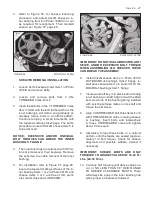
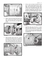
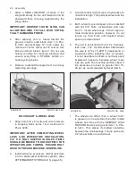
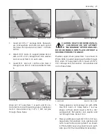
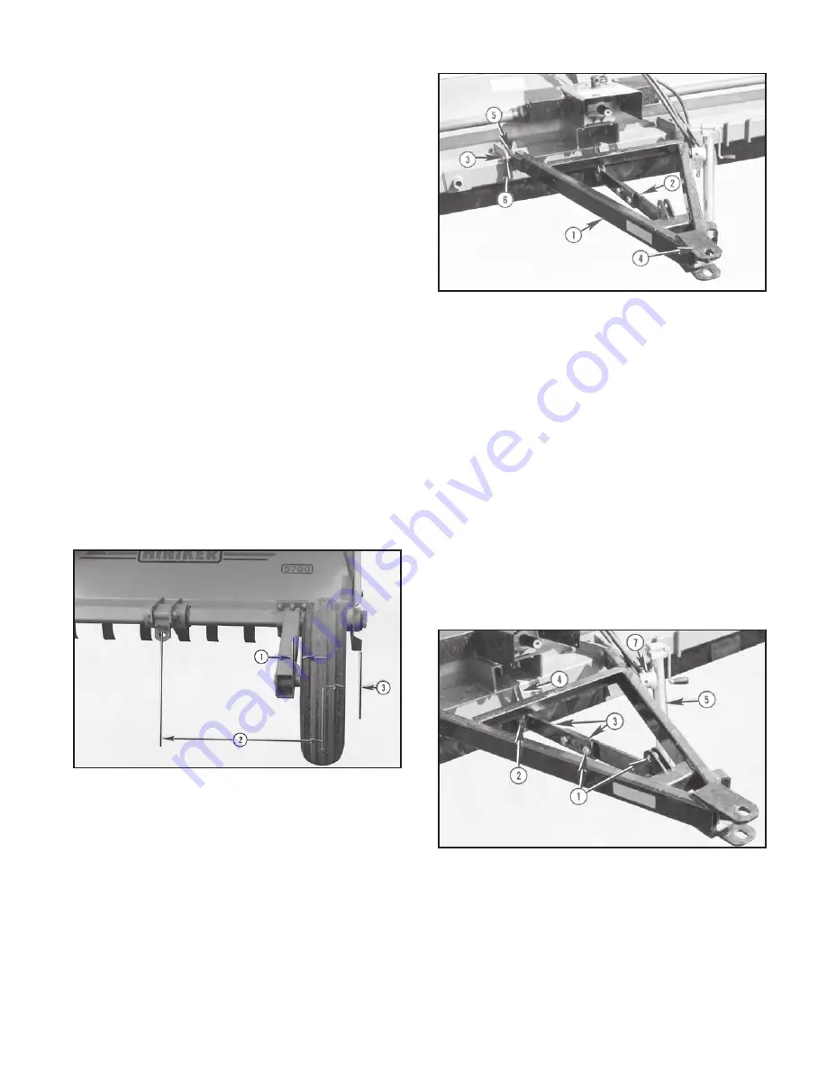
2. FOR ROW CROPS ONLY Item 2 in Photo
3214, position wheel legs to center each tire
34” right or left of the machine’s centerline.
This “compromise” is quite satisfactory for 30”
through 38” row spacings.
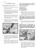
3. FOR SOLID SEEDED CROPS Item 3, in Pho-
to 3214 adjust R.H. wheel leg to position tire’s
outside vertical plane about 3” inside the unit’s
R.H. end panel. This ensures the tire will not
run over uncut crop. The L.H. tire may be po-
sitioned maximum leftward.
4. Torque up each wheel leg’s 6 clamping bolts
by uniformly tightening the lower 3 to snug.
Then torque and retorque, top 3 to
146-206
Ft/Lbs. (198-279 N/m.).
5. Extend the ratchet jack, or hydraulics, to raise
the machine. Remove both previously insert-
ed rear blocks.
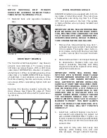
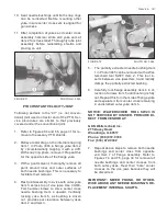
6. Refer to Figure 79, Item 2 and extract 5/8” x 6”
lockup bolt and nut from its shipping position
and insert thru holes Item 3. Ensure the bolt
head faces toward the machine’s centerline.
FIGURE 80 PHOTO NO. 3214
FRONT HITCH
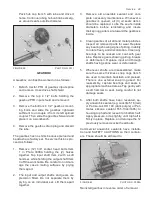
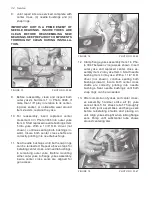
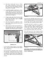
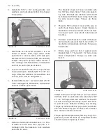
The front hitch bundle consists of the “A”frame
Item 1 as shown in Photo 3555 and a lower adjust-
able draft link Item 2.
Remove both base unit draft pins Item 3 and posi-
tion hitch Item 1 with thicker hitch clip on top Item
4. Insert hitch’s rear brackets Item 5 between both
sets of base unit ears Item 6 and reinstall pins
Item 3. Insure cotters on each end of both pins are
spread.
FIGURE 81 PHOTO NO. 3555
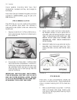
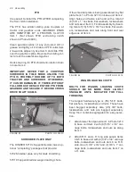
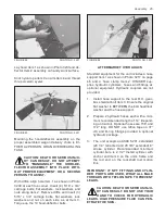
Attach the lower adjustable draft link Item 2 to the
base unit using the pin and cotter pins provided.
Put the adjustable draft link into the second hole
from the top of the “A” frame. Secure using the
pin and cotter pins provided. See Photo 3555.
Adjustable draft link is pre-set for an approxi-
mate 16” drawbar height. This will leave a 3”
stubble height with a ASAE standard hydraulic
cylinder fully closed. However, final adjustment
to a customer’s tractor drawbar height, must
await actual field operation. See Photo 3556.
Move hitch jack Item 5 from shipping position
Item 6 to “use” position Item 7 and raise it suffi-
cient to loosen front center block and remove it.
FIGURE 82 PHOTO NO. 3556
IMPORTANT: AFTER TRACTOR HOOKUP, AL-
WAYS STORE HITCH JACK ON PEDESTAL AT
TOP OF GEARCASE.
Содержание 5710
Страница 2: ......
Страница 12: ...10 Decal Location FIGURE 23 520 03139 Danger Shield Missing FIGURE 24 71504131 Danger Keep Flippers ...
Страница 50: ...NOTES 48 Notes ...

