24 Service
Periodically inspect the rotor assembly for bro-
ken or missing knives. Immediately replace
those so indicated because they will cause the
rotor to run out of balance. HINIKER knives are
sold individually, however to maintain balance.
IMPORTANT: REPLACE KNIVES IN NEAR-
EST OPPOSITE (180° APART) SETS. ALSO,
REPLACE CORRESPONDING IDENTICAL
KNIVES AT OTHER END OF ROTOR.
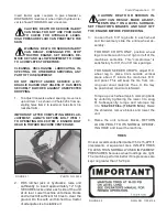
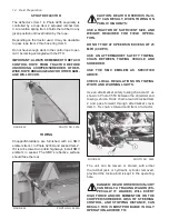
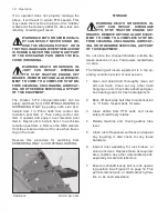
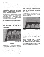
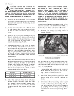
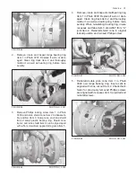
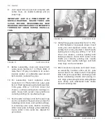
Shredder/choppers are equipped with 32 cup
knives Item 1 in Photo 3215. They are retained
with an equal number of 1/2” x 3” grade 5 car-
riage bolts Item 2, 1/2” x 1 1/4” grade 5 carriage
bolts Item 3 and 64 type B locknuts.
IMPORTANT: WHEN SERVICING KNIVES, AL-
WAYS DISCARD ANY LOCKNUT THAT HAS
BEEN LOOSENED. DO NOT REPLACE HARD-
WARE WITH ORDINARY BOLTS AND NUTS.
INSURE THEY ARE RETORQUED TO 58-82
FT/IBS. (79-112 N/M.). CARRIAGE BOLTS
WITH HEADS ITEM 4, AND NUTS ITEM 5,
SHOULD ALWAYS LEAD DIRECTION OF RO-
TOR ROTATION.
FIGURE 50 PHOTO NO. 3215
SHEARBAR
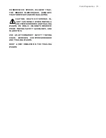
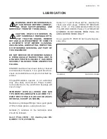
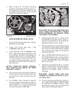
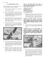
Shearbar Item 1 in Photo 3216 has slots suffi-
cient to give 3/4” fore/aft adjustment. It is factory
adjusted to the furthermost FORWARD position
Item 2. This provides 3/4” theoretical clearance
from the rotor knives. As rotor knives wear, or
better chopping/shredding is needed, move the
shearbar rearward. If knives are worn unevenly,
hold LONGEST knife out toward cutterbar to
check clearance. It is not recommended to adjust
the shearbar closer than 1/4” to the rotor knives.
CLOSER SHEARBAR/ROTOR CLEARANCE
INREASES POWER REQUIREMENTS.
IMPORTANT: THE SHEARBAR IS RETAINED
WITH (6) 1/2” X 1” GRADE 5 CARRIAGE
BOLTS ITEM 3 AND TYPE F LOCKNUTS.
AFTER ANY ADJUSTMENT, INSURE THESE
BOLTS ARE RETORQUED TO 58-82 FT/IBS.
(79-112 N/M.).
Failure to maintain factory bolt torque may cause
loosening and subsequent shearbar entangle-
ment with rotor knives.
FIGURE 51 PHOTO NO. 3216
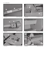
BELTS
HINIKER chopper/shredders are EQUIPPED
ONLY WITH PREMIUM GRADE MATCHED
BELTS. Do not replace these with “garden va-
riety” UNMATCHED belts because their power
transmission capability, and durability, will be
degraded.
NOTICE: ADEQUATE TENSION IS NECES-
SARY FOR FULL POWER TRANSMISSION
AND SATISFACTORY BELT PERFORMANCE.
This is obtained by following instructions on de-
cal located on endplate inside end shield.
Содержание 5710
Страница 2: ......
Страница 12: ...10 Decal Location FIGURE 23 520 03139 Danger Shield Missing FIGURE 24 71504131 Danger Keep Flippers ...
Страница 50: ...NOTES 48 Notes ...

