background image

Technical Data 

113/154 

PC Cards cifX PC/104 | Installation, Operation and Hardware Description  
DOC120206UM42EN | Revision 42 | English | 2014-12 | Released | Public  

© Hilscher, 2008-2014 


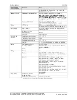
10.1.11  AIFX-DP 

AIFX-DP 

Parameter 

Value 

Name AIFX-DP 
Part No. 

2800.400 

Part 

Description 

PROFIBUS assembly interface (with PROFIBUS interface) 
for the PC cards  
CIFX 104-DP\F, CIFX 104-DP-R\F 

Interface  
PC Card cifX 

Connector 

Cable Connector Fieldbus X1 
(JST 10FMN-SMT-A-TF(LF)(SN), Pitch 1,0 mm) 

Galvanic Isolation 

isolated 

Isolation Voltage 

1000 VDC (tested for 1 minute) 

PROFIBUS Interface 

Connector 

DSub female Connector, 9 pin 
The meaning of the following LEDs depends on the loaded 
firmware: 

ERR 

LED Error status (red) 

STA 

LED Status (green)


Display 

LED Display (on the reverse side 
of the device) 

For PROFIBUS MPI the STA LED is not used.  
Refer to chapter 

LED Descriptions

, page 64.


Power supply 

Connector 

Cable Connector Fieldbus X1 

Operating temperature range* 

-20 °C ... +70 °C 

*Air flow during measurment 

0,5m/s 

Storage temperature range 

-10 °C ... +70 °C 

Humidity 

10 … 95% relative humidity, no condensation permitted 

Environmental 
Conditions 

Environment 

For UL compliant usage:  
The device must be used in a pollution degree 2 
environment. 

Dimensions (L x W x H) 

17 x 31 x 18,5 mm (

H

 = width of the front panel) 

Mounting/Installation 

At the basic cards CIFX 104-FB\F, CIFX 104-FB-R\F:  
Cable Connector Fieldbus X4 (X304) 

Device 

RoHS Yes 

CE Sign 

Yes 

CE Sign 

Emission, Immunity 

Tested together with the corresponding basic card cifX. 

UL Certification 

The device is certified according 
to UL 508 

UL-File-Nr. E221530 

Table 94: Technical Data AIFX-DP 


Содержание CIFX 104

Страница 1: ...nual PC Cards cifX PC 104 CIFX 104 Installation Operation and Hardware Description Hilscher Gesellschaft f r Systemautomation mbH www hilscher com DOC120206UM42EN Revision 42 English 2014 12 Released...

Страница 2: ...egulations 18 1 3 6 Registered Trademarks 18 1 3 7 EtherCAT Disclaimer 19 1 3 8 Obligation to read and understand the Manual 19 1 4 Licenses 19 1 4 1 License Note about VARAN Client 19 2 SAFETY 20 2 1...

Страница 3: ...37 5 DEVICE DRAWINGS 38 5 1 PC Karten cifX PC 104 38 5 1 1 CIFX 104 RE 38 5 1 2 CIFX 104 RE R 39 5 1 3 CIFX 104 RE F 40 5 1 4 CIFX 104 RE R F 41 5 1 5 CIFX 104 DP 42 5 1 6 CIFX 104 DP R 43 5 1 7 CIFX...

Страница 4: ...n Modbus TCP 70 8 10 POWERLINK Controlled Node Slave 71 8 11 PROFINET IO Controller 72 8 12 PROFINET IO Device 73 8 13 sercos Master 74 8 14 sercos Slave 75 8 15 VARAN Client Slave 76 8 16 PROFIBUS DP...

Страница 5: ...YNC Connector X51 CIFX 80 90 104C 94 9 9 2 Items on Hardware 94 9 9 3 Items on Firmware 94 9 10 Pin Assignment at the PC 104 Bus 95 9 10 1 Overview 95 9 10 2 Reference PC 104 Specification 95 9 10 3 P...

Страница 6: ...BUS MPI 131 10 2 16 CANopen Master 132 10 2 17 CANopen Slave 133 10 2 18 DeviceNet Master 134 10 2 19 DeviceNet Slave 135 10 2 20 CC Link Slave 136 11 ANNEX 137 11 1 Matrix Label 137 11 2 EtherCAT Sum...

Страница 7: ...FIBUS DP PROFIBUS MPI CANopen DeviceNet CC Link For information about the Installation of the Software refer to the User Manual Software Installation for PC cards cifX DOC120207UMXXEN For information...

Страница 8: ...Section Technical Data sercos Master updated Section Technical Data sercos Slave updated Section Technical Data CANopen Slave updated Section References updated 41 14 06 18 All 8 14 Items on Safety Me...

Страница 9: ...FX 104 DP R F2 1279 411 2 16 CIFX 104 CO 1278 500 2 1 CIFX 104 CO R 1279 500 2 1 CIFX 104 CO F 3 1278 501 2 1 6 CIFX 104 CO R F 3 1279 501 2 1 6 CIFX 104 DN 1278 510 2 1 CIFX 104 DN R 1279 510 2 1 CIF...

Страница 10: ...INK Controlled Node cifxPLS NXF 2 1 x x from 2 1 22 0 from 2 1 19 0 PROFIBUS DP Master CIFXDPM NXF 2 6 x x from 2 3 22 0 from 2 3 21 0 PROFIBUS DP Slave CIFXDPS NXF 2 7 x x from 2 3 30 0 from 2 3 30 0...

Страница 11: ...ormation Operation Instructions 1 instruction 2 instruction or instruction Results result Safety Messages The labeling of safety messages is explained in the chapter Safety 1 1 4 Used Terminology PC C...

Страница 12: ...view The installation guide includes An overview on the Content of the Communication Solutions DVD in the section What is on the Communication Solutions DVD Overviews listing the available Documentati...

Страница 13: ...mware in your device to version 3 5 Note also SYCON net V1 360 x x can configure the PROFINET IO Device firmware V3 4 as well as V3 5 netX Configuration Tool V1 0510 x x can configure the PROFINET IO...

Страница 14: ...ve firmware in your device to version 4 2 Note also SYCON net V1 360 x x can configure the EtherCAT Slave firmware V2 5 as well as V4 2 10 0 and higher netX Configuration Tool V1 0510 x x can configur...

Страница 15: ...P Master device via EtherNet IP POWERLINK Controlled Node Slave 00000044_CIFX RE PLS xdd For the PROFINET IO Device Firmware V3 4 GSDML V2 3 HILSCHER CIFX RE PNS 20130225 xml PROFINET IO Device For th...

Страница 16: ...accompanying texts and the documentation were created for the use of the products by qualified experts however errors cannot be ruled out For this reason no guarantee can be made and neither juristic...

Страница 17: ...tems air traffic or air traffic communication systems in life support systems in systems in which failures in the software could lead to personal injury or injuries leading to death We inform you that...

Страница 18: ...trademark of QNX Software Systems Ltd VxWorks is a registered trademark of Wind River Systems Inc IntervalZero RTX is a trademark of IntervalZero Adobe Acrobat is a registered trademark of the Adobe S...

Страница 19: ...mage to your system or to your PC card you must read and understand all instructions in the manual and all accompanying texts to your PC card before installing and operating your PC card First read th...

Страница 20: ...anner Master EtherNet IP Scanner Slave CIFX 104 DP CIFX 104 DP R CIFX 104 DP F CIFX 104 DP R F PROFIBUS DP Master PROFIBUS DP Slave PROFIBUS MPI Device Open Modbus TCP POWERLINK Controlled Node Slave...

Страница 21: ...al shock caused by parts with more than 50V may occur if you open the PC cabinet to install the PC card cifX HAZARDOUS VOLTAGE is present inside of the PC or of the connec ting device into which the P...

Страница 22: ...e damage to the PC card cifX A supply voltage below the lower limit can cause malfunction in the PC card cifX The allowed range for the supply voltage is defined by the tolerances specified in this ma...

Страница 23: ...he necessary safety precautions for components that are vulnerable with electrostatic discharge if you install or replace your device Follow the guidelines listed hereafter when you handle this equipm...

Страница 24: ...t in Death or Serious Injury Indicates a minor hazard with medium risk which could have as consequence simple battery if it isn t avoided Indicates a Hazardous Situation Which if not Avoided may Resul...

Страница 25: ...fX proceeds the communication of the corresponding Real Time Ethernet or fieldbus system The used Real Time Ethernet systems are The used fieldbus systems are EtherCAT Master EtherCAT Slave EtherNet I...

Страница 26: ...R DeviceNet Master or Slave connectors at the left side Table 12 PC Cards PC 104 CIFX 104 XX and CIFX 104 XX R 3 3 PC Cards cifX with AIFX Assembly Interfaces 3 3 1 The Label F in the Device Name The...

Страница 27: ...ide Basic card CIFX 104 FB R F and CANopen assembly interface AIFX CO DeviceNet CIFX 104 DN F DeviceNet Master or Slave Basic card CIFX 104 FB F and DeviceNet assembly interface AIFX DN CIFX 104 DN R...

Страница 28: ...04 RE R F CIFX 104 DP CIFX 104 DP R CIFX 104 DP F CIFX 104 DP R F CIFX 104 CO CIFX 104 CO R CIFX 104 CO F CIFX 104 CO R F CIFX 104 DN CIFX 104 DN R CIFX 104 DN F CIFX 104 DN R F CIFX 104 CC F 5 V dc 5...

Страница 29: ...the holes 25 mm CIFX 104 CO F CIFX 104 CO R F AIFX CO Further Information in section CANopen AIFX CO on page 51 Required Cutout for CombiCon male Connector 5 pin Standard cutout D Sub 9 Holes 2x2 dis...

Страница 30: ...nfiguration the firmware download and for the diagnosis note the following notice Important The USB interface the serial interface as well as the cifX Device Driver may only be used exclusively by one...

Страница 31: ...agnostic assembly interface AIFX DIAG 1 3 Reserve Memory Range Interrupt at the operating system Reserve for the PC card cifX the memory range and if necessary one interrupt at the operating system 1...

Страница 32: ...or AIFX DIAG assembly interface to the PC card cifX and check if the connector is plugged in correctly Only then plug another PC 104 module 3 6 Close cabinet Close the cabinet of the PC or connecting...

Страница 33: ...figuration 6 1 Downloading Firmware and Configuration Slave If SYCON net was already used on the PC stop the ODMV3 service Therefore select Service Stop from the context menu of the ODMV3 system tray...

Страница 34: ...sis 8 2 I O Monitor In netDevice rightclick on device symbol Select context menu entry Diagnosis then Tools IO Monitor Check the input or output data See corresponding user manual 9 OR Slave Diagnosis...

Страница 35: ...e Slave to establish communication Important parameters are Vendor ID Product Code Serial Number Revision Number Node ID Output and Input length PROFINET IO Device To configure the Controller a GSDML...

Страница 36: ...me in SYCON net EtherCAT Master Master CIFX RE ECM EtherCAT Slave Gateway Stand Alone Slave CIFX RE ECS EtherNet IP Scanner Master Master CIFX RE EIM EtherNet IP Adapter Slave Gateway Stand Alone Slav...

Страница 37: ...roject files the configuration files and firmware files are to be saved At existing hardware installation the firmware the driver and the configuration software must be updated according to the versio...

Страница 38: ...eckbr cke Datenbusbreite 8 Bit und 16 Bit J9 im Bild Einstellung Steckbr cke f r 16 Bit Data Bus Width Jumpers 8 Bit and 16 Bit J9 Jumper Settings for 16 Bit shown Figure 2 CIFX 104 RE Note Device sup...

Страница 39: ...eite 8 Bit und 16 Bit J9 im Bild Einstellung Steckbr cke f r 16 Bit Data Bus Width Jumpers 8 Bit and 16 Bit J9 Jumper Settings for 16 Bit shown Figure 3 CIFX 104 RE R Note Device supports Auto Crossov...

Страница 40: ...16 Bit J9 im Bild Einstellung Steckbr cke f r 16 Bit Data Bus Width Jumpers 8 Bit and 16 Bit J9 Jumper Settings for 16 Bit shown Figure 4 Basic Card for CIFX 104 RE F Note If the assembly inter face d...

Страница 41: ...J9 im Bild Einstellung Steckbr cke f r 16 Bit Data Bus Width Jumpers 8 Bit and 16 Bit J9 Jumper Settings for 16 Bit shown SYS Figure 5 Basic Card for CIFX 104 RE R F Note If the assembly inter face di...

Страница 42: ...cke Datenbusbreite 8 Bit und 16 Bit J9 im Bild Einstellung Steckbr cke f r 16 Bit Data Bus Width Jumpers 8 Bit and 16 Bit J9 Jumper Settings for 16 Bit shown Interrupt Steckbr cke Interrupt Jumper J8...

Страница 43: ...br cke Interrupt Jumper J8 11 polig 11 pin Adresssteckbr cke Address Jumpers J7 7 polig 7 pin Standardeinstellungen Steckbr cken Default Jumper Settings Steckbr cke Datenbusbreite 8 Bit und 16 Bit J9...

Страница 44: ...Jumper J8 11 polig 11 pin Adresssteckbr cke Address Jumpers J7 7 polig 7 pin Standardeinstellungen Steckbr cken Default Jumper Settings Steckbr cke Datenbusbreite 8 Bit und 16 Bit J9 im Bild Einstell...

Страница 45: ...Jumper J8 11 polig 11 pin Adresssteckbr cke Address Jumpers J7 7 polig 7 pin Standardeinstellungen Steckbr cken Default Jumper Settings Steckbr cke Datenbusbreite 8 Bit und 16 Bit J9 im Bild Einstell...

Страница 46: ...tus LED red green Interrupt Steckbr cke Interrupt Jumper J8 11 polig 11 pin Adresssteckbr cke Address Jumpers J7 7 polig 7 pin je mit Standardbr ckungen Default Jumper Settings each Steckbr cke Datenb...

Страница 47: ...S Interrupt Steckbr cke Interrupt Jumper J8 11 polig 11 pin Adresssteckbr cke Address Jumpers J7 7 polig 7 pin Standardeinstellungen Steckbr cken Default Jumper Settings Steckbr cke Datenbusbreite 8 B...

Страница 48: ...ne jumper must be set If no jumper is set the PC card cifX works in Polling Mode For further details refer to Table 23 Starting Address and Interrupt for 16 KByte Dual Port Memory on page 57 5 1 12 CI...

Страница 49: ...firmware only the RJ45 channel 0 can be used channel 1 is deactivated Beginning with the EtherCAT Master firmware version 3 channel 1 can be reactivated if redundancy is activated For Open Modbus TCP...

Страница 50: ...e X400 9 polig PROFIBUS Interface DSub female Connector X400 9 pin Figure 17 PROFIBUS Assembly Interface AIFX DP Figure 18 Front Side PROFIBUS Assembly Interface AIFX DP flexibles Folienkabel flexible...

Страница 51: ...Sub Stecker X400 9 polig CANopen Interface DSub male Connector X400 9 pin Figure 20 CANopen Assembly Interface AIFX CO Figure 21 Front Side Assembly Interface AIFX CO flexibles Folienkabel flexible fl...

Страница 52: ...nector X360 5 pin Kabelstecker Feldbus Cable Connector Fieldbus X1 10 polig 10 pin 1 2 3 4 5 Figure 23 DeviceNet Assembly Interface AIFX DN Figure 24 Front Side DeviceNet Assembly Interface AIFX DN MN...

Страница 53: ...n Kabelstecker Feldbus Cable Connector Fieldbus X1 10 polig 10 pin Figure 26 CC Link Assembly Interface AIFX CC Figure 27 Front Side CC Link Assembly Interface AIFX CC flexibles Folienkabel flexible f...

Страница 54: ...gr n yellow green Kabelstecker DIAG Cable Connector DIAG X1 12 polig 12 pin SYS COM 0 COM 1 PWR not used not used Figure 29 Diagnostic Assembly Interface AIFX DIAG The meaning of the LEDs at the AIFX...

Страница 55: ...control elements of your device For the installation uninstalling and replacement of the PC card cifX check any notes in the overview in chapter Getting Started on page 31 6 1 Safety Messages on Perso...

Страница 56: ...owed Signaling Voltage Adhere for all PC cards cifX described in this manual the instruction hereafter Device Destruction All I O signal pins at the PC card cifX tolerate only the specified signaling...

Страница 57: ...arch for a free memory area The possible memory areas of 16 KByte are C0000 C3FFF hex D0000 D3FFF hex E0000 E3FFF hex or F0000 F3FFF hex The PC card cifX PC 104 can be used in poll mode or in interrup...

Страница 58: ...errupt in the Device Manager This is Windows ACPI Advanced Configuration and Power Manage ment Interface depending Please check at first if your PC is ACPI compatible and you are using the latest BIOS...

Страница 59: ...tion on the starting address and or an interrupt or polling refer to section cifX PC 104 Set Starting Address and Interrupt on page 57 Depending by the target system motherboard if so set at the PC ca...

Страница 60: ...erface AIFX RE to the basic card Connect the cable connector Ethernet X1 on the AIFX RE with the cable Connect the cable connector Ethernet X4 or X304 on the basic card CIFX 104 RE F or CIFX 104 RE R...

Страница 61: ...G at the front plate of the PC cabinet Important The contacts on the connection cable must face up Figure 34 Connecting the Diagnostic Assembly Interface AIFX DIAG to the Basic Card CIFX 104 FB R F Ex...

Страница 62: ...cabinet Open the cabinet of the PC or of the connecting device Note If a PC card CIFX 104 XX F or CIFX 104 XX R F shall be uninstalled from a stack of PC 104 modules a Remove all PC 104 modules above...

Страница 63: ...f the LED SYS is solid green and the LED COM or COM0 is static green the PC card cifX is in operational state the Master is in data exchange with the connected Slaves and the communication is running...

Страница 64: ...S3 RUN COM 0 Communication Status green green red green green green red green red green orange green ERR ERR NS ERR BE BF ERR ERR COM 1 Communication Status red red red green red red red red red green...

Страница 65: ...ing System Status SYS System Status COM Communication Status RUN Run ERR Error STA Status CAN CANopen Status MNS Module Network Status Communication Status L RUN L ERR Status Run Status Error Table 27...

Страница 66: ...o LED red green off Off Master has no errors ERR Name in the device drawing COM 1 red On Master has detected a communication error The error is indicated in the DPM LED green green On A link is establ...

Страница 67: ...A host watchdog timeout has occurred Possible reason 2 Synchronization Error device enters Safe Operational automatically ERR Name in the device drawing COM 1 red Double Flash Application Watchdog Tim...

Страница 68: ...r If no power is supplied to the device the module status indicator shall be steady off Duo LED red green green On Connected If the device has at least one established connection even to the Message R...

Страница 69: ...If no power is supplied to the device the module status indicator shall be steady off Duo LED red green green On Connected If the device has at least one established connection even to the Message Ro...

Страница 70: ...configured yet OMB task is ready and not configured yet green Flashing cyclic with 5Hz Waiting for Communication OMB task is configured RUN Name in the device drawing COM 0 green On Connected OMB task...

Страница 71: ...ED yellow RJ45 Ch0 Ch1 This LED is not used Table 37 LEDs POWERLINK Controlled Node Controlled Node Slave LED State Definition for POWERLINK Controlled Node Controlled Node Slave for the BS BE LEDs In...

Страница 72: ...h BF red ON No valid Master license SF Name in the device drawing COM 0 red Flashing cyclic at 2 Hz System error Invalid configuration Watchdog error or internal error Duo LED red green off Off No err...

Страница 73: ...ed On Watchdog timeout channel generic or extended diagnosis present system error SF Name in the device drawing COM 0 red Flashing cyclic at 2 Hz for 3 sec DCP signal service is initiated via the bus...

Страница 74: ...to the Ethernet exists green Flickering Activity The device sends receives Ethernet frames L A RJ45 Ch0 Ch1 off Off The device has no connection to the Ethernet LED yellow RJ45 Ch0 Ch1 This LED is no...

Страница 75: ...n Flashing 2 x orange 3 s HP3 Hot plug mode not yet implemented Flashing orange green orange each for 250 ms then green on for 2 seconds and 250 ms orange On CP0 Communication phase 0 orange Flashing...

Страница 76: ...the firmware of the VARAN Client Slave protocol is loaded to the device LED Color State Meaning Duo LED red green green Blinking Configured and communication is inactive green On Configured and commun...

Страница 77: ...annother serious error has occured Redundant Mode The active Master was not found Table 47 LEDs PROFIBUS DP Master 1 Communication Status LED current Hardware Revision 8 16 2 2 Communication Status LE...

Страница 78: ...cyclic STOP no communication connection error COM red Flashing acyclic not configured Table 49 LEDs PROFIBUS DP Slave 1 Communication Status LED current Hardware Revision 8 17 2 2 Communication Statu...

Страница 79: ...e it has not been configured correctly or has a wrong configuration or has not received the PROFIBUS token Table 51 LEDs PROFIBUS MPI 1 Communication Status LED 8 18 2 2 Communication Status LEDs The...

Страница 80: ...ler has reached or exceeded the warning level too many error frames red Double flash Error Control Event A guard event NMT Slave or NMT master or a heartbeat event Heartbeat consumer has occurred CAN...

Страница 81: ...or exceeded the warning level too many error frames red Double flash Error Control Event A guard event NMT Slave or NMT master or a heartbeat event Heartbeat consumer has occurred ERR red On Bus Off...

Страница 82: ...it reached At least one of the error counters of the CAN controller has reached or exceeded the warning level too many error frames red Double flash Error Control Event A guard event NMT Slave or NMT...

Страница 83: ...d or exceeded the warning level too many error frames red Double flash Error Control Event A guard event NMT Slave or NMT master or a heartbeat event Heartbeat consumer has occurred red On Bus Off The...

Страница 84: ...in the established state It has data exchange with at least one of the configured Slaves Minor or recoverable fault No data exchange with one of the configured Slaves One or more Slaves are not conne...

Страница 85: ...in the established state It has data exchange with at least one of the configured Slaves Minor or recoverable fault No data exchange with one of the configured Slaves One or more Slaves are not conne...

Страница 86: ...articipating in the network 2 Unable to detect carrier 3 Timeout 4 Resetting hardware L RUN green On Receive both refresh and polling signals or just the refresh signal normally after participating in...

Страница 87: ...Channel 0 Ethernet Channel 1 Figure 35 Ethernet Pin Assignment at the RJ45 Socket for cifX or AIFX Pin Signal Meaning 1 TX Transmit Data 2 TX Transmit Data 3 RX Receive Data 4 Term 1 5 Term 1 Connect...

Страница 88: ...dden or allowed The following table shows the acceptable use of hubs and switches by each communication system Communication System Hub Switch EtherCAT forbidden only allowed between EtherCAT Master a...

Страница 89: ...ctor Signal Meaning 3 RxD TxD P Receive Send Data P respectively connection B plug 5 DGND Reference potential 6 VP Positive supply voltage 8 RxD TxD N Receive Send Data N respectively connection A plu...

Страница 90: ...with CombiCon male connector Signal Color Description 1 V Black Reference potential DeviceNet supply voltage 2 CAN_L Blue CAN Low Signal 3 Drain Shield 4 CAN_H White CAN High Signal 5 V Red 24 V Devi...

Страница 91: ...4 CO R F CIFX 104 DN R F Note From the hardware revision 5 of the PC cards CIFX 104 RE F and CIFX 104 RE R F if the diagnostic AIFX DIAG assembly interface is connected the Mini B USB connector on the...

Страница 92: ...t for Cable Connector Ethernet X4 or X304 Cable 20 pin Ethernet and Status LEDs Pin Signal 1 GND 2 3V3 Analog 3 STA0_green RE LED COM 0 4 STA0_red RE LED COM 0 5 XM0_TX 6 STA1_green RE LED COM 1 7 CH0...

Страница 93: ...C2_IO1 9 RSTOUT 10 not used Table 75 Pin Assignment for Cable connector Fieldbus X3 X304 or X4 9 8 3 Pin Assignment for Cable Connector DIAG Only for CIFX 104 RE F X303 CIFX 104 RE R F X3 CIFX 104 DP...

Страница 94: ...X51 on page 94 Female connector 3 pin pitch spacing 1 25 mm for example the type Molex series 51021 and female crimp contacts in design e g type Molex series 50079 50058 Max Cable Length Recommendati...

Страница 95: ...ording to the standard Compare Section page PC 104 Specification CIFX 104 RE CIFX 104 RE R CIFX 104 RE F CIFX 104 RE R F CIFX 104 DP CIFX 104 DP R CIFX 104 DP F CIFX 104 DP R F CIFX 104 CO CIFX 104 CO...

Страница 96: ...he PC 104 bus are given in the tables below Pin Assignment for PC 104 Bus X1 Pin X1 A B 1 GND 2 SD7 RESET 3 SD6 5V 4 SD5 IRQ9 5 SD4 6 SD3 7 SD2 8 SD1 9 SD0 10 IOCHRDY GND 2 11 AEN SMEMW 12 SA19 SMEMR...

Страница 97: ...esses can not be specified For maximum performance the IOCHNRDY signal must always be evaluated by the host CPU If you use a host CPU that can not use the IOCHNRDY A10 signal then contact our technica...

Страница 98: ...33 MHz Data Access DPM System Interface Width for the data access to the Dual Port Memory DPM 8 Bit or 16 Bit EtherCAT Master EtherCAT Slave EtherNet IP Scanner Master EtherNet IP Adapter Slave Open M...

Страница 99: ...C 104 Bus Operation Rotary Switch Device Address Is currently unassigned Refer to section Rotary Switch Device Address on page 91 Operating temperature range 0 C 70 C Air flow during measurment 0 5m s...

Страница 100: ...er EtherCAT Slave EtherNet IP Scanner Master EtherNet IP Adapter Slave Open Modbus TCP POWERLINK Controlled Node Slave PROFINET IO Controller Master PROFINET IO Device Slave sercos Master sercos Slave...

Страница 101: ...mA Power supply Connector Via PC 104 Bus Operating temperature range 0 C 70 C Air flow during measurment 0 5m s Storage temperature range 0 C 70 C Environmental Conditions Humidity 10 95 relative humi...

Страница 102: ...n Rate 9 6 kBit s 19 2 kBit s 31 25 kBit s 45 45 kBit s 93 75 kBit s 187 5 kBit s 500 kBit s 1 5 MBit s 3 MBit s 6 MBit s 12 MBit s Interface Type RS 485 refer to section PROFIBUS Interface page 89 Ga...

Страница 103: ...DP R F CIFX 104 DP F CIFX 104 DP R F Parameter Wert Name CIFX 104 DP F CIFX 104 DP R F Part No 1278 411 1279 411 Description PC Card cifX PC 104 PROFIBUS DP Master or Slave and PROFIBUS MPI Device co...

Страница 104: ...imum Current at at 5 V typically 500 mA Power supply Connector Via PC 104 Bus Operating temperature range 20 C 70 C Air flow during measurment 0 5m s Storage temperature range 10 C 70 C Environmental...

Страница 105: ...it s 50 kBit s 100 kBit s 125 kBit s 250 kBit s 500 kBit s 800 kBit s 1 MBit s Interface Type ISO 11898 refer to section CANopen Interface page 89 Galvanic Isolation isolated optically isolated Isolat...

Страница 106: ...04 CO R F Parameter Value Name CIFX 104 CO F CIFX 104 CO R F Part No 1278 501 1279 501 Description PC Card cifX PC 104 CANopen Master or Slave composed of Basic card CIFX 104 FB F or CIFX 104 FB R F w...

Страница 107: ...104 Bus Operating temperature range 20 C 70 C Air flow during measurment 0 5m s Storage temperature range 10 C 70 C Environmental Conditions Humidity 10 95 relative humidity no condensation permitted...

Страница 108: ...kBit s 500 kBit s Interface Type ISO 11898 according to DeviceNet specification refer to section DeviceNet Interface page 90 Galvanic Isolation isolated optically isolated Isolation Voltage 1000 VDC t...

Страница 109: ...104 DN F CIFX 104 DN R F Part No 1278 511 1279 511 Description PC Card cifX PC 104 DeviceNet Master or Slave composed of Basic card CIFX 104 FB F or CIFX 104 FB R F with cable connector Fieldbus X4 X3...

Страница 110: ...umidity no condensation permitted Dimensions L x W x H 97 x 91 x 24 mm Mounting Installation PC 104 Slot 5 V refer to section Slot for the PC Cards cifX PC 104 page 28 Device RoHS Yes CE Sign Yes Emis...

Страница 111: ...e CC Link assembly interface AIFX CC to the basic card CC Link Interface Connector AIFX CC Cable Connector Fieldbus X4 JST 10FMN SMT A TF LF SN Pitch 1 0 mm Diagnostic Assembly Interface AIFX DIAG ref...

Страница 112: ...erface Connector 2 RJ45 Socket The meaning of the following LEDs depends on the loaded firmware COM 0 LED Communication Status 0 duo LED COM 1 LED Communication Status 1 duo LED LED yellow LED green a...

Страница 113: ...LED Status green Display LED Display on the reverse side of the device For PROFIBUS MPI the STA LED is not used Refer to chapter LED Descriptions page 64 Power supply Connector Cable Connector Fieldbu...

Страница 114: ...ERR LED Error status red RUN LED Run green Display LED Display on the reverse side of the device Refer to chapter LED Descriptions page 64 Power supply Connector Cable Connector Fieldbus X1 Operating...

Страница 115: ...e of the device The meaning of the MNS LED is depending on loaded firmware Refer to chapter LED Descriptions page 64 Power supply Connector Cable Connector Fieldbus X1 Operating temperature range 20 C...

Страница 116: ...r CombiCon male Connector 5 polig L RUN LED L Run Duo LED L ERR LED L Error Duo LED Display LED Display on the reverse side of the device Refer to chapter LED Descriptions page 64 Power supply Connect...

Страница 117: ...munication Status 0 duo LED COM 1 LED Communication Status 1 duo LED Display LED Display Refer to chapter LED Descriptions page 64 Power supply Connector Kabelstecker DIAG X1 Operation Rotary Switch D...

Страница 118: ...Maximum 1500 bytes Functions Get OD List Get object description Get entry description Emergency Slave diagnostics Bus Scan Supported Redundancy Supported but not at the same time with Distributed Cloc...

Страница 119: ...ted 32 Bit Baud rate 100 MBit s Data transport layer Ethernet II IEEE 802 3 Limitation LRW is not supported Reference to firmware stack version V2 5 x x and V4 2 x x Table 100 Technical Data EtherCAT...

Страница 120: ...er of input and output data Maximum number of unscheduled data 1400 bytes per telegram UCMM Class 3 Supported Explicit Messages Client and Server Services Get_Attribute_Single All Set_Attribute_Single...

Страница 121: ...ons 8 explicit and implicit connections Unconnected Message Manager UCMM Supported Quick connect Supported Predefined standard objects Identity Object Message Route Object Assembly Object Connection M...

Страница 122: ...Client using the Command Table The data is stored in the I O process data image Client using the packet API The I O process data image is not used Server using the packet API The I O process data ima...

Страница 123: ...ion Protocol CL RPC Connectionless Remote Procedure Call Context management by CL RPC Supported Minimum cycle time 1 ms Different IO Devices can be configured with different cycle times Functions Fast...

Страница 124: ...CMP Ping Topology recognition LLDP SNMP V1 MIB2 physical device VLAN and priority tagging yes Context Management by CL RPC Supported Identification Maintenance Read and write of I M1 4 Minimum cycle t...

Страница 125: ...1 ms for RT_CLASS_1 250 s for RT_CLASS_3 IRT Support RT_CLASS_3 Media Redundancy MRP client is supported Additional features DCP VLAN and priority tagging Shared Device Baud rate 100 MBit s Data trans...

Страница 126: ...s 511 Minimum cycle time 250 s Acyclic communication Service channel Read Write Commands Functions Bus Scan Communication phases NRT CP0 CP1 CP2 CP3 CP4 Topology Line and double ring Redundancy suppor...

Страница 127: ...n Communication Specification Version 1 1 2 Supported sercos Communication Profiles SCP_FixCFG Version 1 1 1 SCP_VarCFG Version 1 1 1 SCP_VarCFG Version 1 1 3 Supported User SCP Profiles SCP_WD Versio...

Страница 128: ...tes Memory Area Read Memory Area 1 Write Memory Area 1 Functions Memory Read Memory Write Integrated 2 port splitter for daisy chain topology Supported Baud rate 100 MBit s Data transport layer Ethern...

Страница 129: ...c communication DPV1 class 1 read write DPV1 class 1 alarm DPV1 class 2 initiate read write data transport abort Maximum number of acyclic read write 240 bytes per slave and telegram Functions Configu...

Страница 130: ...ata 237 bytes application specific parameters Acyclic communication DP V1 Class 1 Read Write DP V1 Class 1 Alarm DP V1 Class 2 Read Write Data Transport Baud rate 9 6 kBits s 19 2 kBits s 31 25 kBits...

Страница 131: ...ons MPI Read Write DB data block M marker Q output C Counter T Timer MPI Read I Input Data type bit to access to DB data block M marker Q output and I Input read only MPI Connect automatically when fi...

Страница 132: ...fer synchronized remotely requested and event driven change of date Acyclic communication SDO Upload Download max 512 bytes per request Functions Emergency message consumer and producer Node guarding...

Страница 133: ...cation SDO upload download server only Emergency message producer Timestamp producer consumer Functions Node guarding life guarding Heartbeat 1 producer max 64 consumer PDO mapping NMT Slave SYNC prot...

Страница 134: ...on Maximum Configuration data 1000 bytes slave Acyclic communication Explicit connection All service codes are supported Connections Bit Strobe Change of State Cyclic Poll Explicit Peer to Peer Messag...

Страница 135: ...output data 255 bytes Acyclic communication Get_Attribute_Single All Max 240 bytes per request Set_Attribute_Single All Max 240 bytes per request Connections Poll Change of state Cyclic Bit strobe Exp...

Страница 136: ...les 1 2 4 8 Baud rates 156 kBit s 625 kBit s 2500 kBit s 5 MBit s 10 MBit s Limitation Intelligent Device Station not supported Firmware works according to CC Link Version 1 11 Station Types Remote I...

Страница 137: ...Summary over Vendor ID Conformance test Membership and Network Logo 11 2 1 Vendor ID The communication interface product is shipped with Hilscher s secondary vendor ID which has to be replaced by the...

Страница 138: ...ance requirements For example certain communication parameters are set by a software stack in which case the actual software implementation in the device application determines whether or not the netw...

Страница 139: ...ll duplex mode Affected Hardware Hardware with the communication controller netX 50 netX 100 or netX 500 netX Internal PHYs When can this Failure occur When using standard Ethernet communication with...

Страница 140: ...3 Hilscher GmbH 2013 EtherCAT Master Protocol API Manual V3 Revision 5 Hilscher GmbH 2013 EtherCAT Slave Protocol API Manual Revision 3 V4 Hilscher GmbH 2013 EtherCAT Slave Protocol API Manual Revisio...

Страница 141: ...Display CANopen Assembly Interface AIFX CO 51 Figure 23 DeviceNet Assembly Interface AIFX DN 52 Figure 24 Front Side DeviceNet Assembly Interface AIFX DN 52 Figure 25 Dimensioning and LED Display Dev...

Страница 142: ...on of the Master Device 36 Table 22 Device Names in SYCON net by Communication Protocol 36 Table 23 Starting Address and Interrupt for 16 KByte Dual Port Memory 57 Table 24 Overview LEDs Real Time Eth...

Страница 143: ...able 73 Pin Assignment Mini B USB Connector 91 Table 74 Pin Assignment for Cable Connector Ethernet X4 or X304 92 Table 75 Pin Assignment for Cable connector Fieldbus X3 X304 or X4 93 Table 76 Pin Ass...

Страница 144: ...Device Protocol 125 Table 108 Technical Data sercos Master Protocol 126 Table 109 Technical Data sercos Slave Protocol 127 Table 110 Technical Data VARAN Client Protocol 128 Table 111 Technical Data P...

Страница 145: ...egotiation Auto Negotiation is a feature of an interface An interface with Auto Negotiation will automatically determine a set of correct communication parameters Baud rate Data transmission speed of...

Страница 146: ...for each CC Link device Device Description File A file containing configuration information about a device being a part of a network that can be read out by masters for system configuration Device De...

Страница 147: ...identical for DP and FMS Firmware Software running inside a device providing the basic functionality of this device The firmware is stored remanently in the flash memory circuit of the device It can...

Страница 148: ...ommunication in both directions is called a half duplex telecommunication system At such a system receiving data inhibits the transmission of data Half duplex is the opposite of _Full_duplex Hub A net...

Страница 149: ...ease of notation the IP address is divided into four 8 bit numbers which are represented in decimal notation and separated by points a b c d where a b c d are each integer values between 0 and 255 Exa...

Страница 150: ...of reading back the inputs to read the outputs MPI Multi Point Interface The MPI is a proprietary interface of the SIMATIC S7 series of PLCs It is compatible to PROFIBUS and based on RS 485 It usuall...

Страница 151: ...Express CIFX 50E Low Profile PCI Express CIFX 70E CIFX 100EH RE CUBE Compact PCI CIFX80 Mini PCI CIFX90 Mini PCI Express CIFX 90E PC 104 CIFX 104 and as Communication Interface netX with PC 104 ISA Bu...

Страница 152: ...ingle register or multiple registers sequentially located can be accessed Modbus differs Input Registers FC 4 and Holding Registers FC 3 6 16 23 Remanent Remanent memory holds its data even after powe...

Страница 153: ...watchdog timer provides an internal supervision mechanism of a communication system It supervises that an important event happens within a given timeframe the watchdog time which can be adjusted acco...

Страница 154: ...o hilscher fr Support Phone 33 0 4 72 37 98 40 E Mail fr support hilscher com India Hilscher India Pvt Ltd New Delhi 110 065 Phone 91 11 26915430 E Mail info hilscher in Italy Hilscher Italia S r l 20...

Отзывы: