Annex
142/154
PC Cards cifX PC/104 | Installation, Operation and Hardware Description
DOC120206UM42EN | Revision 42 | English | 2014-12 | Released | Public
© Hilscher, 2008-2014
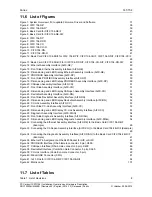
Table 2: Reference on Hardware PC Cards cifX, AIFX Assembly Interfaces
9
Table 3: Reference on Driver and Software
9
Table 4: Reference on Firmware
10
Table 5: PROFINET IO-Device Firmware Version 3.4 and 3.5, Header, GSDML and Protocol API Manual 13
Table 6: EtherCAT-Slave Firmware Version 2.5 and 4.2, Header, XML and Protocol API Manual
14
Table 7: Device Description Files for PC Cards cifX
15
Table 8: PC Cards cifX and the Real-Time Ethernet or Fieldbus Systems realized thereby
20
Table 9: PC Cards cifX with AIFX Assembly Interface
20
Table 10: Signal Words and Safety Signal in Safety Messages on Personal Injury
24
Table 11: Signal Words and Safety Signal in Safety Messages on Property Damage
24
Table 12: PC Cards PC/104: CIFX 104-XX and CIFX 104-XX-R
26
Table 13: PC Cards PC/104: CIFX 104-XX\F, CIFX 104-XX-R\F
27
Table 14: AIFX Assembly Interfaces for PC Cards cifX with Cable Connector
27
Table 15: Slot for the PC Cards cifX PC/104
28
Table 16: Requirements Power Supply and Host Interface for PC Cards cifX PC/104
28
Table 17: Panel Cutout at the at the front plate of the PC cabinet
28
Table 18: Required Panel Cutout and Holes for AIFX
29
Table 19: Requirements to operate PC Cards cifX properly
30
Table 20: Steps for the Software and Hardware Installation, the Configuration and for the Diagnosis of a PC
Card cifX PC/104 (Master and Slave)
34
Table 21: Notes for the Configuration of the Master Device
36
Table 22: Device Names in SYCON.net by Communication Protocol
36
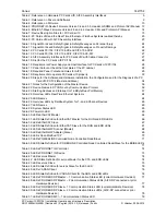
Table 23: Starting Address and Interrupt for 16 KByte Dual-Port Memory
57
Table 24: Overview LEDs Real-Time Ethernet Systems
64
Table 25: LED Names
64
Table 26: Overview LEDs by Fieldbus System for 1- and 2-Channel Devices
65
Table 27: LED Names
65
Table 28: System Status LED
65
Table 29: Power On LED
65
Table 30: LEDs EtherCAT Master
66
Table 31: LED State Definition for EtherCAT Master for the RUN and ERR LEDs
66
Table 32: LEDs EtherCAT Slave
67
Table 33: LED State Definition for EtherCAT Slave for the RUN and ERR LEDs
67
Table 34: LEDs EtherNet/IP Scanner (Master)
68
Table 35: LEDs EtherNet/IP Adapter (Slave)
69
Table 36: LEDs Open Modbus/TCP
70
Table 37: LEDs POWERLINK Controlled Node Controlled Node/Slave
71
Table 38: LED State Definition for POWERLINK Controlled Node Controlled Node/Slave for the BS/BE LEDs
71
Table 39: LEDs PROFINET IO-Controller
72
Table 40: LEDs PROFINET IO-Device
73
Table 41: LEDs sercos Master
74
Table 42: LED State Definition for sercos Master for the STA and ERR LEDs
74
Table 43: LEDs sercos Slave
75
Table 44: LED State Definition for sercos Slave for the S3 LED
76
Table 45: LEDs VARAN Client
76
Table 46: LED State Definition for VARAN Client for the RUN and ERR LEDs
76
Table 47: LEDs PROFIBUS DP Master – 1 Communication Status LED (current Hardware Revision)
77
Table 48: LEDs PROFIBUS DP Master – 2 Communication Status LEDs (AIFX-DP connected or prior
Hardware Revision)
77
Table 49: LEDs PROFIBUS DP Slave – 1 Communication Status LED (current Hardware Revision)
78
Table 50: LEDs PROFIBUS DP Slave – 2 Communication Status LEDs (AIFX-DP connected or prior
Hardware Revision)
78
Table 51: LEDs PROFIBUS MPI – 1 Communication Status LED
79


