User Manual of Mobile Digital Video Recorder
17
correct, and then perform the following steps:
Steps:
1.
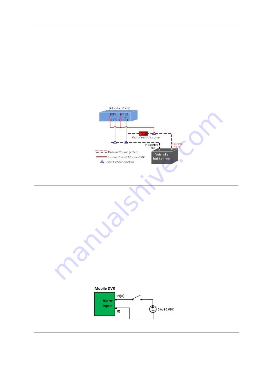
Connect the “DC IN +” and “KEY +” of mobile DVR to the positive pole of vehicle batteries, jumping over the switch
of normal vehicle power.
2.
Connect the “DC IN -” to the negative pole of vehicle batteries.
3.
Connect the “KEY -” of mobile DVR to the vehicle ignition switch.
1.4.5
Timing On/Off
Figure 1. 6
Timing On/Off
Steps:
1.
Connect the “DC IN +” and “KEY +” of mobile DVR to the positive pole of vehicle batteries.
2.
Connect the “DC IN -” and “KEY -” of mobile DVR to the negative pole of vehicle batteries.
For detailed time settings of time-delay shutdown, see
10.1 Configuring Startup and Shutdown
1.5
Alarm Input/Output Connection
1.5.1
Alarm Input Connection
DS-MP7508 series mobile DVR adopts the high/low-level electrical signals triggering (high level: 6 to 36 VDC; low level: 0
to 5 VDC) to realize alarm input. And in order to avoid error report caused by voltage fluctuation, no alarm will be triggered
by voltage ranging of 5 to 6 VDC.
Figure 1. 7
Alarm Input Connection


