


HAULOTTE GROUP
5 CYLINDER REPLACEMENT
72
TELESCOPING
BOOM
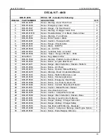
BASE END
CYLINDER
RETAINER
PIN
CYLINDER
SLAVE
ROD END
UPPER BOOM
JIB BOOM
CYLINDER
PIN
PIVOT
PIN
MASTER / SLAVE CYLINDER REPLACEMENT (CONTINUED)
Master Cylinder (Continued)
Place absorbent cloths below the cylinder ports and detach hydraulic hoses from the cylinder.
Elevate hoses to prevent leakage. Plug or cap exposed hose fittings and cylinder ports.
Unbolt and remove the pin retainer at the base end of the cylinder.
Remove the pivot pin using a hammer and a brass or hardwood drift.
Replace or reinstall the cylinder by following the above instructions in the reverse order of
removal.
Actuate the hydraulic system and check for leakage. Tighten hydraulic fittings as needed.
Bleed trapped air from the hydraulic system by raising and lowering the telescoping boom with the
reservoir fill port cap on, but not tightened. Allow several cycles of operation for trapped air to
escape. Repeat as necessary
.
Slave Cylinder
Refer to Figure 5–2 for the location of this cylinder.
With the boom in the “stowed” position, extend the telescoping boom until there is adequate
exposure of the pin retainer and pivot pin (approximately 2 ft. (0.7 m)).
Verify that the upper boom is supported by lifting straps and an overhead hoist or equivalent.
Unbolt and remove the pin retainer at the rod end of the cylinder.
Remove the pivot pin using a hammer and a brass or hardwood drift.
Tag and number all hydraulic hoses that attach to the cylinder valve block. Use a marker to label
the valve block ports with the appropriate hose numbers.
Place absorbent cloths below the cylinder ports and detach hydraulic hoses from the cylinder.
Elevate hoses to prevent leakage. Plug or cap exposed hose fittings and cylinder ports.
Unbolt and remove both pin retainers at the base end of the cylinder.
Remove the pivot pin using a hammer and a brass or hardwood drift.
Replace or reinstall the cylinder by following the above instructions in the reverse order of
removal.
Actuate the hydraulic system and check for leakage. Tighten hydraulic fittings as needed.
Bleed trapped air from the hydraulic system by raising and lowering the telescoping boom with the
reservoir fill port cap on, but not tightened. Allow several cycles of operation for trapped air to
escape. Repeat as necessary.
Figure 5-2. Location of Slave Cylinder
Содержание xlb-4725a
Страница 1: ...OPERATOR S MAINTENANCE MANUAL B33 01 0104 Rev 4 August 2012...
Страница 70: ...HAULOTTE GROUP 5 CYLINDER REPLACEMENT 70...
Страница 78: ...HAULOTTE GROUP 6 DECAL REPLACEMENT 78 DECAL KIT ANSI...
Страница 80: ...HAULOTTE GROUP 6 DECAL REPLACEMENT 80 IDENTIFICATION PLATES OPTIONAL EQUIPMENT ANSI...
Страница 86: ...HAULOTTE GROUP 6 DECAL REPLACEMENT 86...
Страница 92: ...HAULOTTE GROUP 7 OPTIONAL EQUIPMENT 92...
Страница 98: ...HAULOTTE GROUP 8 MATERIAL SAFETY 98 MATERIAL SAFETY DATA SHEET POWERFLOW AW HVI HYDRAULIC OIL...
Страница 99: ...HAULOTTE GROUP 8 MATERIAL SAFETY 99 MATERIAL SAFETY DATA SHEET POWERFLOW AW HVI HYDRAULIC OIL CONTINUED...
Страница 100: ...HAULOTTE GROUP 8 MATERIAL SAFETY 100 MATERIAL SAFETY DATA SHEET POWERFLOW AW HVI HYDRAULIC OIL CONTINUED...
Страница 101: ...HAULOTTE GROUP 8 MATERIAL SAFETY 101 MATERIAL SAFETY DATA SHEET POWERFLOW AW HVI HYDRAULIC OIL CONTINUED...
Страница 102: ...HAULOTTE GROUP 8 MATERIAL SAFETY 102 MATERIAL SAFETY DATA SHEET POWERFLOW AW HVI HYDRAULIC OIL CONTINUED...
Страница 103: ...HAULOTTE GROUP 8 MATERIAL SAFETY 103 MATERIAL SAFETY DATA SHEET POWERFLOW AW HVI HYDRAULIC OIL CONTINUED...
Страница 104: ...HAULOTTE GROUP 8 MATERIAL SAFETY 104 MATERIAL SAFETY DATA SHEET POWERFLOW AW HVI HYDRAULIC OIL CONTINUED...
Страница 116: ...HAULOTTE GROUP 9 ANSI REPRINT 116...