


HAULOTTE GROUP
3 OPERATION
30
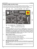
NORMAL OPERATING PROCEDURE (CONTINUED)
Become familiar with the location and function of all controls. Learn to smoothly
START
and
STOP
all
boom functions.
At the ground (lower) control panel, turn the
KEY SWITCH
(1)
counter clockwise to the
GROUND
CONTROLS
(1a)
icon. If power does not come on, make sure that both of the
EMERGENCY STOP
buttons;
GROUND
(6),
and
PLATFORM
(5),
are pulled out and the main power disconnect plug is
plugged in.
The control microprocessor will perform self-diagnostics to test the operating system. After
several seconds, the
DISPLAY PANEL
window will read:
HAULOTTE GROUP
ACCESS SOLUTIONS
Monitor the battery condition indicator during operation and charge the batteries as necessary.
Extend the four outriggers individually, or for simultaneous extension use the
AUTO LEVEL
(23)
button on the ground (lower) control panel. When the aerial work platform is leveled properly, a
buzzer will sound, the two LEDs at each
OUTRIGGER
(25
and
26)
button, and the LED at the
AUTO
LEVEL
(23)
button will be lit. Refer to Figure 3-5.
Figure 3-5. Outrigger Control Panel
o
Auto Level:
Press (push) and hold the
EXTEND
(21)
and
AUTO LEVEL
(23)
buttons at the same
time.
o
Manual Level:
Extend the two outriggers closest to the trailer coupler first. Lower the front
pair of outriggers by pressing (pushing) the
EXTEND
(21)
button and the two front
OUTRIGGER
buttons at the same time. Lower the back pair of outriggers by pressing (pushing) the
EXTEND
(21)
button and the two back
OUTRIGGER
buttons at the same time.
Verify that the
AUTO LEVEL
(23)
indicator LED is lit. If the
A
UTO
L
EVEL
(23)
indicator is not lit, the
aerial work platform may not be level, and the weight of the machine may not be on the outrigger
foot pad.
NOTE:
If the boom is not level or if one or more outriggers are not supporting the
machines load the safety interlock system prevents all boom operations.
NOTE:
The Range of Motion Diagrams at the ground (lower) and platform (upper) control
stations displays the range of platform motion (safe operating zone). Verify that the
operating zone is clear of obstructions through 700º of Non-Continuous rotation.
Содержание xlb-4725a
Страница 1: ...OPERATOR S MAINTENANCE MANUAL B33 01 0104 Rev 4 August 2012...
Страница 70: ...HAULOTTE GROUP 5 CYLINDER REPLACEMENT 70...
Страница 78: ...HAULOTTE GROUP 6 DECAL REPLACEMENT 78 DECAL KIT ANSI...
Страница 80: ...HAULOTTE GROUP 6 DECAL REPLACEMENT 80 IDENTIFICATION PLATES OPTIONAL EQUIPMENT ANSI...
Страница 86: ...HAULOTTE GROUP 6 DECAL REPLACEMENT 86...
Страница 92: ...HAULOTTE GROUP 7 OPTIONAL EQUIPMENT 92...
Страница 98: ...HAULOTTE GROUP 8 MATERIAL SAFETY 98 MATERIAL SAFETY DATA SHEET POWERFLOW AW HVI HYDRAULIC OIL...
Страница 99: ...HAULOTTE GROUP 8 MATERIAL SAFETY 99 MATERIAL SAFETY DATA SHEET POWERFLOW AW HVI HYDRAULIC OIL CONTINUED...
Страница 100: ...HAULOTTE GROUP 8 MATERIAL SAFETY 100 MATERIAL SAFETY DATA SHEET POWERFLOW AW HVI HYDRAULIC OIL CONTINUED...
Страница 101: ...HAULOTTE GROUP 8 MATERIAL SAFETY 101 MATERIAL SAFETY DATA SHEET POWERFLOW AW HVI HYDRAULIC OIL CONTINUED...
Страница 102: ...HAULOTTE GROUP 8 MATERIAL SAFETY 102 MATERIAL SAFETY DATA SHEET POWERFLOW AW HVI HYDRAULIC OIL CONTINUED...
Страница 103: ...HAULOTTE GROUP 8 MATERIAL SAFETY 103 MATERIAL SAFETY DATA SHEET POWERFLOW AW HVI HYDRAULIC OIL CONTINUED...
Страница 104: ...HAULOTTE GROUP 8 MATERIAL SAFETY 104 MATERIAL SAFETY DATA SHEET POWERFLOW AW HVI HYDRAULIC OIL CONTINUED...
Страница 116: ...HAULOTTE GROUP 9 ANSI REPRINT 116...