MODU-FIRE
®
Forced Draft Gas-Fired Boiler 2500-3000
17
All boiler venting systems should be designed by a qualified venting professional ex-
perienced in venting system design. The information contained herein should be used as a guide only and is
not intended to be used in lieu of qualified technical expertise.
3.5.3.2 Required
Clearances
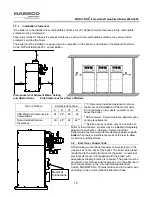
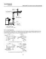
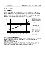
Provide clearances between combustion air intake, exhaust vent, roof and wall surfaces, doors and window, and
snow line. Refer to Figure below: Termination Clearances – Forced Draft and Direct Vent Installations.
Conventional Vent Systems
The following termination clearance requirements are for conventional, non-direct vent installations.
The vent system shall terminate at least 3 ft above a forced air inlet that is within 10 feet horizontally.
The vent system shall terminate at least 4 ft below, 4 ft horizontally from or 1 ft above any door, operable win-
dow or gravity inlet into any building. The bottom of the vent terminal shall be at least 12 in. above grade or
highest expected snow line (if applicable).
Through the wall terminations shall not terminate over public walkways or over an area where condensate or
vapor could create a nuisance or hazard or could be detrimental to the operation of regulators, relief valves or
other equipment.
Direct Vent (Sealed Combustion) Systems
The vent terminal shall be located at least 12 in. from any air opening into a building. The bottom of the vent
terminal shall be at least 12 in. above grade. Both the vent and air intake terminals must be at least 12 in.
above the highest expected snow line.
Do not locate intake or exhaust terminations directly above a walkway;
dripping of condensation can cause icing of the walking surface. Maintain a minimum clearance of 4
ft (1.22 m) horizontally from any electric or gas meter, regulator or relief equipment.
Содержание 1004905923
Страница 2: ...MODU FIRE Forced Draft Gas Fired Boiler 2500 3000 2 ...
Страница 31: ...MODU FIRE Forced Draft Gas Fired Boiler 2500 3000 31 Ratio V Adjust at Hi Fire Bias N Adjust at Low Fire ...
Страница 45: ...MODU FIRE Forced Draft Gas Fired Boiler 2500 3000 45 6 1 3 Wiring Schematic ...
Страница 48: ...MODU FIRE Forced Draft Gas Fired Boiler 2500 3000 48 6 1 6 Rear Junction Box ...
Страница 49: ...MODU FIRE Forced Draft Gas Fired Boiler 2500 3000 49 6 1 7 Customer Connections ...
Страница 56: ...MODU FIRE Forced Draft Gas Fired Boiler 2500 3000 56 ...

