


MODU-FIRE
®
Forced Draft Gas-Fired Boiler 2500-3000
16
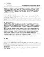
NOTICE!
1. The free area of a combustion air supply opening is calculated by deducting the blockage area of any fixed
louvers, grilles or screens from the total area of the opening.
2. Screens shall be not smaller than ¼”
3. Motorized louvers shall be interlocked with the appliance so that they are proven open prior to main burner
ignition and operation
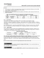
Table of Canadian Minimum Area of Combustion and Ventilation Air Openings
MFD
Required Combustion Air Opening
Ventilation Air Opening
Model #
Input (Btu/Hr)
in
2
mm
2
in
2
mm
2
N2500 2,500,000
83.3
53,763
10
6,452
N3000 3,000,000
100
64,516
10
6,452
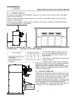
3.5.3
Flue Venting
This boiler is not certified for use with Type "B" vent nor with any type of plastic venting.
This boiler is a Category IV appliance (condensing – positive pressure) as it is defined in ANSI Z21.13/CSA 4.9,
latest edition. The vent material must be as described in section 3.5.1.2. The exhaust vent can be run horizontal-
ly or vertically.
Vent installations shall be in accordance with NFPA54/ANSI Z223.1, the
National Fuel Gas Code
, or CAN/CSA-
B149.1, the
Natural Gas and Propane Installation Code
, or applicable provisions of the local building codes.
3.5.3.1 VENT
SIZING
The vent must be sized in accordance with the ASHRAE Systems and Equipment handbook, Chapter 30 or ac-
cording to the vent manufacturer’s recommendations. When using manufactured venting systems, consult your
vent supplier for correct sizing and structural support requirements.
Table of Vent Design Parameters
MFD Model
Frictional
Resistance
Stack
Temperature
CO
2
Natural Gas
CO
2
LP Gas
N2500/N3000 1.0”
Max 300°F (gross)
8.5%
10.3%
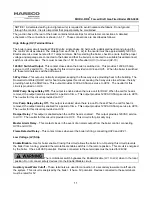
The vent must be sized according to the vent manufacturer’s recommendations.
Consult your vent supplier
for correct sizing and structural support requirements. Design calculations should be based on a positive
pressure at the flue collar, not to exceed 1.0 inch W.C. with a stack temperature of 300° F (gross) and a CO
2
level of 8.5% natural gas. The vent should be designed to provide positive pressure at the flue collar at all firing
rates.
NOTICE! Refer to example in section 3.5.5 regarding pressure drop across the boiler.
Do not use a barometric damper with this boiler
. This is a positive pressure sys-
tem. Flue gases may leak into the room.
This equipment
MUST NOT
be used with a heat actuated automatic vent damper.
Содержание 1004905923
Страница 2: ...MODU FIRE Forced Draft Gas Fired Boiler 2500 3000 2 ...
Страница 31: ...MODU FIRE Forced Draft Gas Fired Boiler 2500 3000 31 Ratio V Adjust at Hi Fire Bias N Adjust at Low Fire ...
Страница 45: ...MODU FIRE Forced Draft Gas Fired Boiler 2500 3000 45 6 1 3 Wiring Schematic ...
Страница 48: ...MODU FIRE Forced Draft Gas Fired Boiler 2500 3000 48 6 1 6 Rear Junction Box ...
Страница 49: ...MODU FIRE Forced Draft Gas Fired Boiler 2500 3000 49 6 1 7 Customer Connections ...
Страница 56: ...MODU FIRE Forced Draft Gas Fired Boiler 2500 3000 56 ...