MODU-FIRE
®
Forced Draft Gas-Fired Boiler 2500-3000
18
Through the wall terminations shall not terminate over public walkways or over an area where condensate or
vapor could create a nuisance or hazard or could be detrimental to the operation of regulators, relief valves or
other equipment.
When multiple direct vent appliances are adjacent, the exhaust must terminate at least 10 feet horizontally or
three feet vertically from the air intake of another appliance.
Interior Component Installation Clearances
All vent system components shall be installed so as to maintain the following required minimum clearances:
Vent Type and Clearance Type
Combustible Surface
Non-Combustible Surface
UL 1738 listed Category IV vent
Per manufacturer’s listing
Per manufacturer’s listing
3.5.3.3 Flue
Connection
The boiler vent should not be connected into any portion of another mechanical
draft system without consulting the vent manufacturer. This boiler operates under a positive vent pressure.
The boiler shall not be connected to any part of a vent system serving a Category I or II appliance, nor shall a
Category I or II appliance be connected to any part of the vent system serving this appliance. Improper inter-
connection of venting systems may result in leakage of flue gases into occupied spaces.
NOTICE!
Make sure that the weight of the vent is
not supported
by the boiler vent collar.
The collar is not
designed to support the weight of the vent.
The vent system shall be supported in accordance with the
manufacturer’s instructions. Horizontal vent sections shall be supported in a manner to prevent sags or low
spots where condensate can collect. Structural supports must be connected to building elements of sufficient
strength to withstand the weight of the vent system and any bending forces imposed by the venting system.
This boiler has 10” OD connections for the vent. If venting design permits, this connection may be reduced to 8”
diameter. The connection from the boiler to the vent should be made using an adapter that is designed to fit the
OD of the boiler outlet. The vent manufacturer’s adapter must be sealed to the boiler outlet with sealant listed for
use with the vent material. The connection from the boiler to the vent should be as direct as possible and the
upward slope of any horizontal breaching should be at least ¼ inch per linear foot. Provisions must be made for
supports to prevent contact of the vent with combustible surfaces.
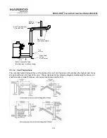
The complete exhaust with drain system is shown in the figures below. The appliance connector should
incorporate provisions to drain condensate formed in the vent system. The first turn from horizontal to vertical
should be made with either a standard tee with condensate drain cap or an elbow with an “inline” drain installed
immediately above the elbow. The condensate drain line from the boiler must be connected to the stack drain
upstream of the stack trap using a material that will withstand condensate corrosion and a maximum temperature
of 400°F. The stack trap shall have a minimum height of 4 inches. The condensate must be routed to a suitable
drain that complies with all local codes.
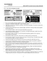
The boiler condensate drain line can get as hot as the stack. This may be up to
400ºF. This line should be insulated to prevent thermal injury or burns.
Do NOT use copper or plastic for the boiler condensate line, as these may fail and
allow exhaust gas to leak into the room.
Содержание 1004905923
Страница 2: ...MODU FIRE Forced Draft Gas Fired Boiler 2500 3000 2 ...
Страница 31: ...MODU FIRE Forced Draft Gas Fired Boiler 2500 3000 31 Ratio V Adjust at Hi Fire Bias N Adjust at Low Fire ...
Страница 45: ...MODU FIRE Forced Draft Gas Fired Boiler 2500 3000 45 6 1 3 Wiring Schematic ...
Страница 48: ...MODU FIRE Forced Draft Gas Fired Boiler 2500 3000 48 6 1 6 Rear Junction Box ...
Страница 49: ...MODU FIRE Forced Draft Gas Fired Boiler 2500 3000 49 6 1 7 Customer Connections ...
Страница 56: ...MODU FIRE Forced Draft Gas Fired Boiler 2500 3000 56 ...

