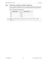
© 2012 Harmonic Inc.
48
Electra 1000, Version 3.0, Rev M
Appendix C
Encoder Back Panel Slot Locations
C.1 Adapter Configurations for All Encoders
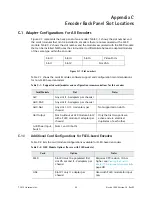
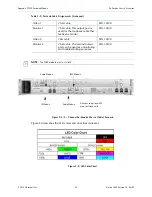
Figure C-1 represents the back panel of an encoder. Table C-1 shows the slot number and
the cards/modules that can be installed in encoders that are not associated with a FLEX
module. Table C-2 shows the slot number and the modules associated with the FLEX module
that can be installed. NMX uses the slot number to differentiate between adapters/modules
of the same type within the encoder.
Figure C-1: Slot numbers
Table C-1 shows the cards/modules, software support and configuration recommendations
for non-FLEX based encoders.
C.1.1
Additional Card Configurations for FLEX-based Encoders
Table C-2 lists the card/module configurations available for FLEX-based encoders.
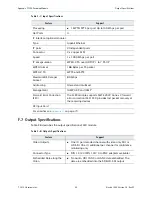
Table C-1: Supported cards/modules and configuration recommendations for this encoder
Card/Module
Slot
Notes
AIC
Any slot (1-5 adapters per chassis)
AHC-RAC
Any slot (1-5 adapters per chassis)
AHC-561
Any slot 1-4 (1- 4 adapters per
chassis)
Not supported on slot 5.
ASI Output
Slot 5 without a FLEX module. Slot 2
with a FLEX module. (1 adapter per
chassis).
Only the first two ports are
active and are electrical
duplicates of each other.
A/B Power Input
Switch
Slots 1 and 3 (both)
Table C-2: FLEX Module Options (for use with FLEX module)
Card
Option
Notes
FLEX
Slot #4 must be populated first,
slot #5 second (1-2 adapters per
chassis)
Requires CPC revision 105 or
higher. see
Board (CPC) Revision Information
GbE
Slot #1 only (1 adapter per
chassis)
Used with FLEX module for input
only
Slot 3
Slot 4
Slot 5
Video Ports
Slot 1
Slot 2
Slot 255

