Chapter 2 Introduction
Back Panel
© 2012 Harmonic Inc.
16
Electra 1000, Version 3.0, Rev M
2.9.4
Modes of Operation
There are three modes of operation on the encoder and are set globally through the NMX
interface for all encoder platforms and locally on SAG as well.
Default Mode
Verbose Front Panel Mode
NMX Control Over Second Line
2.9.4.1
Default Mode
The default mode (with no provision from the NMX application) is the default mode. For more
information on the default mode refer to the NMX online help
2.9.4.2
Verbose Front Panel
The front panel displays the device name on line one and either the card number or
Broadcast Operations Control (BOC) as well as the (sliding) service name on the second line.
For more information on the verbose front panel refer to the NMX online help
2.9.4.3
NMX Control Over Second Line
Under this option you can the front panel classic display mode as well as channel name and
bitrate. For more information on the NMX control on the second line refer to the NMX online
help.
2.10 Back
Panel
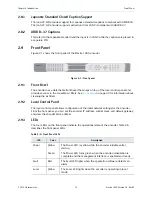
The back panel contains the following elements, as shown in Figure 2-2:
NOTE:
Refer to
on page 48 for information on which adapters/cards/modules are supported in
your back panel.
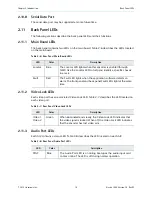
Activity
Yellow
The Activity LED lights when the encoder generates an MPEG-2
transport stream. It blinks slowly when MPEG packets are being
transmitted steadily. It blinks fast or intermittently when the
transmission rate is slow or intermittent.
AC power plug and fuse or DC power
supply
Up to ten stereo digital and analog audio
input ports (two stereo digital audio
input ports per AIC)
Up to four video input ports
Video lock LEDs
Fault relay port
Fault and Locator LEDs
Serial data input port (reserved for future
use)
One 10/100 Base-T Ethernet
management port
One 10/100/1000 Base-T Fast Ethernet
output port with second redundant
channel and connector
Table 2-5: Front Panel LEDs
continued
LED
Color
Description

