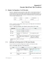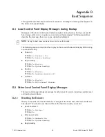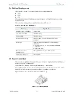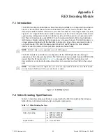
Appendix C Encoder Back Panel Slot Locations
Adapter Configurations for All Encoders
© 2012 Harmonic Inc.
49
Electra 1000, Version 3.0, Rev M
NOTE:
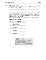
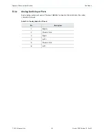
ASI Input modules (used with FLEX module) and ASI Output modules utilize the same hardware,
but perform different functions based on; 1) the slot number and 2) if a FLEX module is installed. If
installed in slots #2 or 5 the ASI module is always an output, If a FLEX module is installed, an ASI module
installed in slots #1 or 3 is an input.
C.1.2
Viewing the Control Board (CPC) Revision Information
1.
From the Platform tab click on the Platform link.
2.
Click on the Control Board (CPC) link.
The Control Board (CPC) Configuration page appears.
3.
Click on the Maintenance tab to examine the version information.
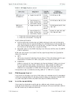
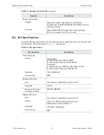
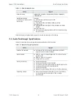
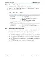
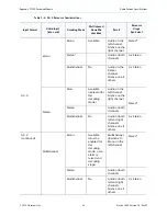
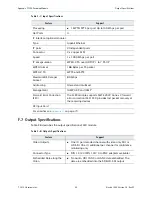
ASI Input
Slot #1 (typical), slot #3 if slot 1 is
already in use (1 card per
chassis). For FLEX only chassis,
the FLEX module goes into slot
#4 and #5. Slot #4 must be
populated first. For baseband and
compressed mixed input
encoders, the FLEX module can
be either slot #4 or #5. ASI input
adapters cannot use slot #4 as it
is used for first FLEX module.
ASI input is currently only for
FLEX. module. ASI in slots 1, 3,
and 4 appears as an input card.
RF 8VSB
Slot #1 (typical), or slot #3 if slot
1 is already in use, or slot # 2 if
slots 1 and 3 are already in use.
(1 card per chassis)
Used with FLEX module for input
only.
Table C-2: FLEX Module Options (for use with FLEX module)
Card
Option
Notes

