Installation and Setup
25
Hardware Reference Manual – DXLink™ Twisted Pair 4K Transmitters/Receivers
NetLinx Binding of DXLink Receiver Modules with an Enova DGX Switcher
IMPORTANT:
The information in this section does not pertain to the 4K HDMI Wallplate TX as the device does not communicate with
or receive control from NetLinx Studio.
NOTE:
If a DXLink module has been configured for auto-setup mode and then auto-setup mode has been disabled, the unit may take
longer to appear in NetLinx Studio than expected (1-2 minutes).
DXLink Modules
must
have their DIP switch toggles set before they will display as part of an Enova DGX system in NetLinx Studio
(v4.0 or later is required). DIP switch information, including settings for common scenarios, is on the next three pages.
In NetLinx Studio, the DXLink Modules can be bound to the integrated Master by right-clicking on the device and selecting Network
Bind/Unbind Device. This is considered the traditional method of binding. Auto-setup information (which does not require binding)
is available in the
Hardware Reference Manual – Enova DGX 100 Series Digital Media Switchers
.
To bind DXLink Modules to Enova DGX integrated Master:
1.
Verify the following:
a.
Verify that an Ethernet/RJ-45 cable is connected from the Enova DGX Switcher’s integrated Master to the network
(e.g., from the switcher’s LAN 100/1000 port to a LAN).
b.
Verify that the target Module is connected via its DXLink connector to a DXLink Input or Output Board on the switcher.
c.
Verify that the switcher is powered on.
2.
Launch NetLinx Studio and open the OnLine Tree.
3.
Bind the target Module to the integrated Master:
a.
Select and right-click the Module.
b.
From the context sensitive menu, select Network Bind/Unbind Device (be sure the check box is selected).
c.
Click OK.
DIP Switch Location
TIP:
For easiest access to the DIP switch toggles, we recommend setting them before installation.
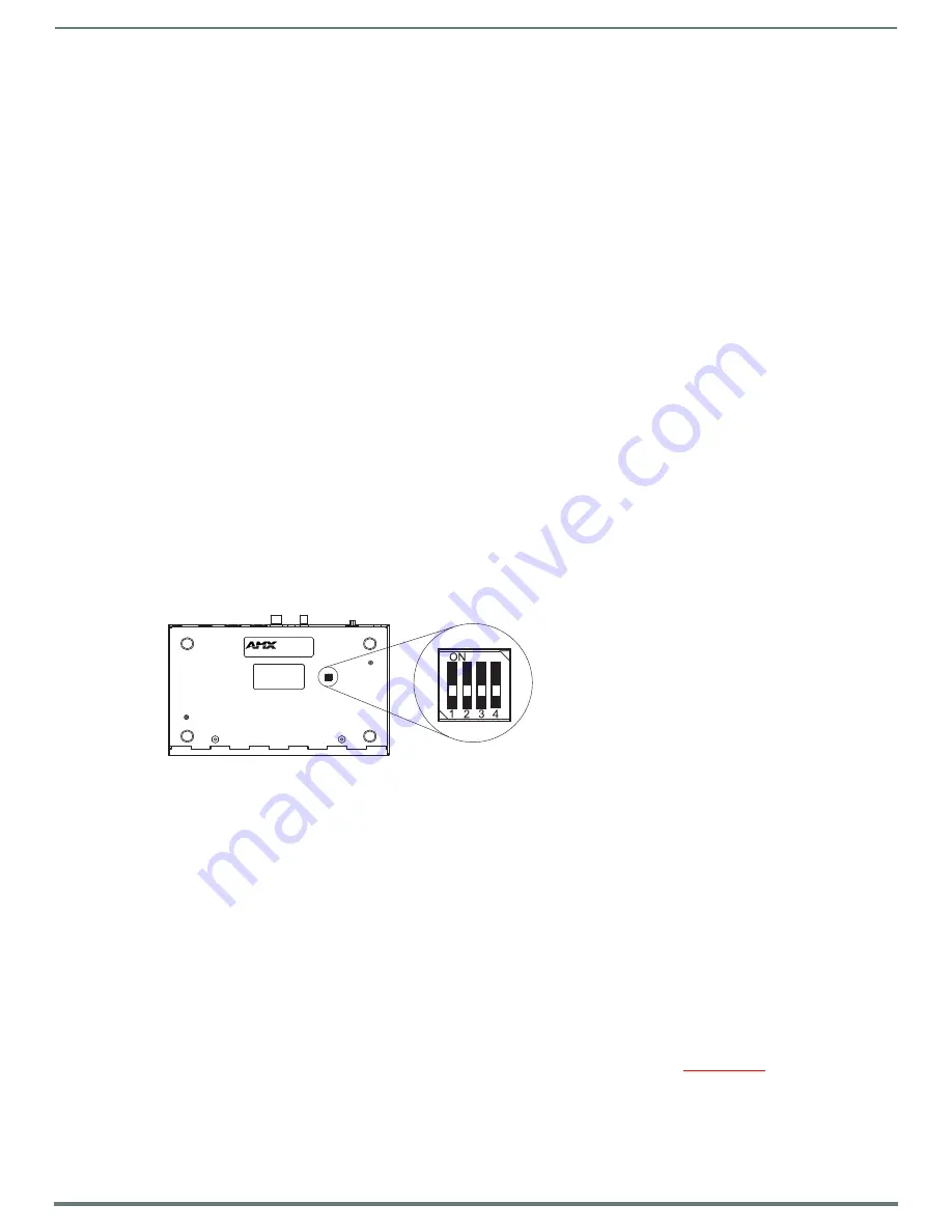
DIP switch toggles for enabling/disabling special DXLink Module functionality are located on the bottom of the Receiver Module
NOTE:
DIP switch settings are read only on reboot. After the settings are read, any adjustments of the toggles will not be implemented
and will not affect the system.
Setting DIP Switch #1 to Enable/Disable Access to ICS LAN 10/100 Port
The #1 Toggle is used for enabling/disabling network activity over the physical ICS LAN 10/100 port, which allows Ethernet
passthrough. It does not affect network activity over DXLink. (For SEND_COMMANDs to disable/enable ICS LAN functionality, see
NOTE:
Toggle settings do not apply to the 4K HDMI Wallplate TX.
TIP:
Common setup scenarios and their DIP switch settings are provided in a table on page 27.
#1 Toggle Settings
OFF
(default) – When the #1 Toggle is set to OFF, network activity over the ICS LAN 10/100 port is disabled.
ON
– When the #1 Toggle is set to ON, network activity over the ICS LAN 10/100 port is enabled.
When a DXLink Module is connected to a DXLink input or output on an Enova DGX Digital Media Switcher or Solecis 4K Digital
Switcher, the switcher provides a network connection allowing the device to appear in the online tree in NetLinx Studio (#3 Toggle
must
be set to ON). For connecting a DXLink Module to other equipment using the ICS LAN 10/100 port, the #1 Toggle
must
be set
to ON.
CAUTION:
Because the DXLink connection carries network activity passed from the switcher, do not connect the ICS LAN 10/100
port on a DXLink Module to the same LAN as the switcher because a network loop will result (see page 24).
FIG. 12
DIP switch on bottom of Receiver Module
DX-RX-4K
DIP switch


