27
Subject to change without notice
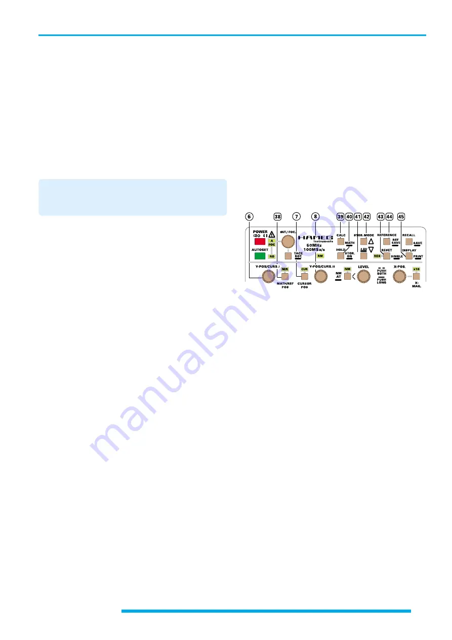
“Set” confirms the settings and switches the MATHE-
MATIC menu off. If the setting is “[x] Display .....” the last
calculated result is displayed on the screen. Briefly pressing
the CALC – MATH [39] pushbutton initiates a new
calculation and it`s display.
To the right of the mathematic signal, the information M1,
M2 or M3 is displayed depending on the selected MATH
(1, 2 or 3) function, if the identification (DISPLAY [45]) is
activated.
The mathematic signal can be switched off by calling
MATH, switching “x” off in the lowest line, and leaving
the menu with “Set”.
39.1.5 Calculation of equation(s).
If several equation lines are activated, to be displayed
as one result, batch processing is performed. If all
equation lines are activated, the processing sequence
is lines 1., 2., 3., 4. and 5.
All 5 equations can be activated ([x]) but not more then one
result (MATH1, MATH2 or MATH3) can be displayed.
The result of an equation can be used in a subsequent
equation as an operand as long as both equations are
activated.
If for example the 5 equations are activated and each result
is defined as e.g. “MAT3”, equation line “5.” will later be
displayed under suited conditions.
Inactivated equations will not be calculated and skipped, if
an active equation follows.
39.2 CALC.
The following description presumes that the
MATHEMATIC menu settings are suited for “mathematic
signal” display.
Briefly pressing causes a new calculation under the actual
signal conditions, and consequently the display of the
updated result. Each time a signal or equation change has
been made, a new calculation must be made to start a
calculation under the new conditions and display the result.
The scaling of the mathematic signal displayed is made
automatically and is independent of the graticule and
deflection coefficients, and is not displayed. Thus the
determination of the mathematic signal height must be
performed by a CURSOR (V to GND). As a minimum of 2
signals are being displayed (CHI or CHII and MATH) the
measuring value display must be set by the SOURCE (33)
pushbutton for mathematic signal measurement (Y:M.....).
It is required to change the “V to GND” CURSOR position
after “CALC” (calculation) to update the measurement
display.
If a division by zero has been made, the readout briefly
displays the warning “DIVISION BY ZERO!” (incorrect
operation).
[40] HOLD – STOR. ON
- Pushbutton with double function.
STOR. ON
Pressing and holding switches over from analog to storage
(digital) mode and vice versa. In the case of CT (Component
Tester) mode active, this mode must be left before it is
possible to switch over from analog to digital mode.
In analog mode, the sampling rate information (“....S”) is
not shown (in the top left readout position) nor signal
display mode information (sgl, rfr, env, avm) (bottom right
readout position).
As the time coefficient ranges are not identical, they taken
into account if necessary when switching over from from
analog to digital (storage) mode and vice versa. The
differences are explained under item (22) TIME/DIV. where
description of the different signal capture modes can also
be found.
Attention!
The possibilities of delayed trace and the related operations
with delayed time base are not available in digital mode,
although the +/- 100% continuously variable pretrigger
function will achieve most requirements.
Additional information regarding digital mode can be
found in section “Storage mode”.
HOLD
STORAGE MODE ONLY
Briefly pressing switches the HOLD function on or off.
The current contents of the memory are protected against
overwriting when “hld” is displayed in the readout, instead
of channel information (e.g.
”Y1“
,
”Y2“
resp.
”X“
and
”Y“
in XY mode). This prevents a change of the Yt mode
setting, but it is possible to select between DUAL (Yt) and
XY display by pressing the DUAL (16) pushbutton if one of
these modes was selected before activating ”hld“ (HOLD).
Particularly when slow time base settings are present in
“rfr” (refresh) signal display modes (rfr, env, avm), one can
observe how the existing memory contents are successively
overwritten by new data, if HOLD is switched off. Protecting
the memory contents in the middle of a data acquisition
process can result in an irregularity at the junction of old
(right) and new data (left). This can be avoided by recording
in single shot mode (“sgl”), even though the input signal is
repetitive. At the end of a sweep, one can use “hld” (HOLD)
to protect the contents against being overwritten by an
unintentional actuation of RESET (RES).
The signal in each of the current memories can be shifted
in the vertical direction (+/- 4cm) with the corresponding Y-
POS rotary knob when “hld” is operative.
Attention!
The dynamic range limits of the A/D converter may
become visible if a Y-position shift is performed after
storage. This can affect those signal parts which were
originally above or below the screen.
[41] STOR. MODE - #AV - Pushbutton
[42] STOR. MODE - Pushbutton
STORAGE MODE ONLY
Controls and readout


