background image

2-10


2. Local Mode Screen

4.

LAN Setting

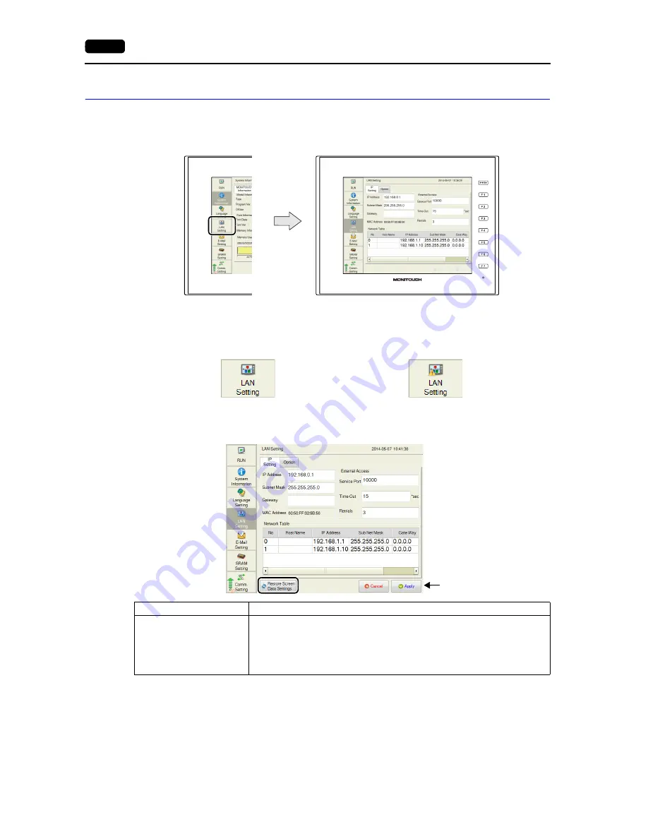
Pressing [LAN Setting] in the menu icons brings up the LAN Setting screen.
This screen is used to set an IP address of the V9 series unit.

When no LAN cable is connected or a link is not established, the indication of the [LAN Setting] icon is 
changed as follows.

Item

Description

Restore Screen Data 
Settings

Restores the screen program settings after the IP settings were changed on the 
V9 series unit.

* When settings are restored, the changes made on the unit are cancelled.

For details on the handling of a screen program changed in Local mode, refer to 
page 2-55.

Menu icons

LAN Setting screen

Link established

Cable disconnected or link not established

Press the [Apply] switch 
to confirm the setting.

LAN Setting screen

Содержание Monitouch V9 Series

Страница 1: ...Troubleshooting Maintenance Manual ...

Страница 2: ...Record of Revisions Reference numbers are shown at the bottom left corner on the back cover of each manual Printing Date Reference No Revised Contents June 2014 1068NE0 First edition ...

Страница 3: ...on 6 and explains macro editor operations and macro command descriptions in detail 1071NE V9 Series Hardware Specifications Explains the hardware specifications and handling procedures of the MONITOUCH V9 series 2023NE V9 Series Connection Manual 1 Explains the connection and communication parameters for the V9 series and controllers in detail 2210NE V9 Series Connection Manual 2 2211NE V9 Series ...

Страница 4: ...f the lithium battery in fire Failure to follow these conditions will lead to explosion or ignition Never use a lithium battery that is deformed leaking or shows any other signs of abnormality Failure to follow these conditions will lead to explosion or ignition The power lamp flashes when the backlight has reached the end of its service life or when the backlight is faulty Note that the switches ...

Страница 5: ...t repair disassemble or modify the V9 series Hakko Electronics Co Ltd is not responsible for any damages resulting from repair disassembly or modification of the unit that was performed by an unauthorized person Do not use sharp pointed tools to press touch switches Doing so may damage the display unit Only experts are authorized to set up the unit connect cables and perform maintenance and inspec...

Страница 6: ...ol If a data receive error occurs when the V9 series unit and a counterpart unit PLC temperature controller etc are started at the same time read the manual of the counterpart unit to correctly resolve the error Avoid discharging static electricity on the mounting panel of the V9 series Static charge can damage the unit and cause malfunctions Discharging static electricity on the mounting panel ma...

Страница 7: ...creen 1 Switching to Local Mode 2 1 2 Local Mode Screen 2 2 Composition of Local Mode Screens 2 3 1 RUN 2 4 2 System Information 2 5 2 1 MONITOUCH Information 2 5 2 2 Screen Data Information 2 6 2 3 Driver Information 2 6 2 4 H W Information 2 7 3 Language Setting 2 8 3 1 Language Setting 2 8 3 2 Keyboard 2 9 4 LAN Setting 2 10 4 1 IP Setting 2 11 4 2 Option 2 15 5 E Mail Setting 2 16 5 1 Connecti...

Страница 8: ...ge 2 41 11 5 Message Dialog Displayed during Data Transfer between V9 and Storage 2 42 12 I O Check 2 43 12 1 Touch Switch 2 44 12 2 Network Test 2 47 12 3 Duplicate IP Test 2 49 13 User Settings 2 50 3 Handling Data Changed in Local Mode 2 55 Chapter 3 Error Handling 1 Error Messages 3 1 1 Setup Error 3 1 2 Screen Program Error 3 1 2 1 Error Numbers 3 2 3 Communication Error 3 9 3 1 Error Message...

Страница 9: ...11 Before Operation 2 Function Switches 3 System Menu 4 Status Bar MONITOUCH Operations ...

Страница 10: ...tting procedures refer to the V9 Series Connection Manual 3 Turn on the power to the V9 series unit 4 After turning on the power to the V9 series unit for the first time in step 3 select an interface language for the unit 5 Transfer the screen program created using the V SFT editor For details on screen program transfer refer to page 1 2 6 Start operation When the connection with controllers has b...

Страница 11: ...V9 series unit For more information on 1 to 3 refer to the V9 Series Setup Manual 4 Transfer from storage Use a storage device such as an SD card or a USB flash drive Load a screen program from the PC into the storage device in advance When turning on the power to MONITOUCH for the first time the Transfer Using Storage switch appears at the center of the screen Pressing this switch displays the St...

Страница 12: ...gram F1 to F7 Switches The function switches can be operated by the user when the V9 series unit is in RUN mode in operation and the system menu is not displayed by pressing the SYSTEM switch 1 Function switches should be defined on V SFT version 6 Settings for each screen Screen Setting Local Function Switch Setting Local Function Switch Setting window Settings for all screens 2 System Setting Gl...

Страница 13: ...splayed only when the security function is enabled using V SFT version 6 For details on the operating procedure refer to page 1 7 For details on the security function refer to the V9 Series Reference Manual Operation Log Displayed only when the operation log function is enabled using V SFT version 6 This is used for displaying the operation log viewer For details on the operation log function and ...

Страница 14: ...eckbox is selected the Status Bar Prohibited checkbox is also selected automatically When the System Switch Prohibited checkbox is selected the system menu is not displayed in RUN mode but it is displayed in Local mode Notes Any switches that are hidden by the system menu are disabled while the system menu is showing The system menu has priority even over scrolling messages When the SYSTEM switch ...

Страница 15: ...ways ON is selected for Action in the System Setting Unit Setting Backlight tab window in V SFT version 6 The backlight setting can be changed on the V9 series unit as well For details refer to Backlight Setting page 2 28 When in RUN mode in operation When the backlight control device memory is used and it is set to 0 4 This is valid only when communication with the connected device is correctly e...

Страница 16: ... Login Logout switch For details on how to display the system menu refer to page 1 5 2 Enter a user name and a password and press the Log In switch 3 The security level is set to 4 and the previous screen is displayed Login is prohibited for users with a security level lower than that of the currently displayed screen If such an attempt is made the message Level does not match appears Item Descrip...

Страница 17: ... switch For details on how to display the system menu refer to page 1 5 2 Press the Log Out switch 3 The security level is reset to 0 and the previous screen is displayed When logout is executed the security level is set to zero 0 Since the previous screen is displayed again logout must be done on a lower security screen Password entry not required Current security level and user name ...

Страница 18: ...play the system menu refer to page 1 5 2 The administrator authentication screen is displayed Enter an administrator name and password and press the OK switch 3 Registered user accounts are listed as shown below Press Security in the system menu or press the SYSTEM switch to hide the system menu Then administrator authentication is automatically cancelled To display the user list by pressing Secur...

Страница 19: ...ator privileges select the Grant administrator privileges checkbox The user name must be unique The same password can be set for multiple users 3 Press the OK switch to add the user account to the list Administrator privileges Operations that can be performed on the V9 series unit differ depending on whether or not the user has administrator privileges User With administrator privileges Without ad...

Страница 20: ...e confirmation dialog shown below is displayed To delete press the OK switch 3 The selected user account is deleted from the list Only accounts registered on MONITOUCH can be deleted Accounts registered in the screen program cannot be deleted Only the account of the user currently logged in authenticated as well as users with no administrator privileges granted can be deleted Accounts of other adm...

Страница 21: ...ch 2 Change the settings 3 After change press the Apply or OK switch The settings are updated Only accounts registered on MONITOUCH can be edited Accounts registered in the screen program cannot be edited Only the account of the user currently logged in authenticated as well as users with no administrator privileges granted can be edited Accounts of other administrator users cannot be edited ...

Страница 22: ...ge Removal switch regardless of the operation mode RUN or Local Chapter 2 For details on the Storage Removal switch refer to the V9 Series Reference Manual Item Description SD Card C Connection status Displays the connection status of the SD card inserted into the SD card slot Remove Reconnect Removes or reconnects the SD card For details refer to page 1 14 USB Storage D Connection status Displays...

Страница 23: ...ove switch under SD Card C 3 When the removal completes the display is changed as shown below Reconnecting the Storage Device This section explains how to reconnect the SD card after Removing the Storage Device page 1 14 1 Display the system menu and press the Storage Removal switch For details on how to display the system menu refer to page 1 5 2 Press the Reconnect switch under SD Card C 3 When ...

Страница 24: ...les stored in the storage device selected at 1 Select a file or folder to copy move to 4 Drive selection destination of copy move Select a storage device to which data is to be copied or moved 5 Path destination of copy move Displays the path to the selected file or folder 6 Directory selection Select a directory in the storage device selected at 4 as a copy or move destination 7 Copy Copies the s...

Страница 25: ...ted to the USB A port 1 Display the system menu and press the Storage Viewer switch For details on how to display the system menu refer to page 1 5 2 Select a file to copy as well as its destination and press the Copy switch 3 The following confirmation dialog appears Press the OK switch The selected file is copied This completes the copy ...

Страница 26: ...h drive connected to the USB A port 1 Display the system menu and press the Storage Viewer switch For details on how to display the system menu refer to page 1 5 2 Select a file to move as well as its destination and press the Move switch 3 Press the Move switch The following confirmation dialog appears Press the OK switch This completes the move ...

Страница 27: ...the system menu refer to page 1 5 2 Select a file to delete and press the Delete switch 3 The following confirmation dialog appears Press the OK switch The selected file is deleted This completes the deletion The file or folder selected in the left pane is deleted Note that the file or folder selected in the right pane will not be deleted The file or folder selected in the right pane will not be d...

Страница 28: ... at all times If valid the status bar is displayed at all times even after the operation mode is switched over between RUN and Local VNC connection This icon is shown during connection with the VNC client When the client is disconnected the icon disappears For details refer to page 1 21 LAN connection Indicates the link status of the LAN connection For details refer to page 1 22 PLC 8WAY connectio...

Страница 29: ...nt 1 When the status bar is set to display at all times it will not disappear 2 It will not disappear when the detailed status information is displayed Prohibiting the Status Bar When the System Switch Prohibited or Status Bar Prohibited checkbox is selected in the System Setting Unit Setting System Mode Switch tab window the status bar cannot be displayed When the System Switch Prohibited or Stat...

Страница 30: ...nstead VNC Connection This icon is displayed when the VNC server is used on the V9 series unit with the client connected When the client is disconnected the icon disappears When the VNC Connection icon is pressed by the client during connection the following confirmation dialog appears Pressing the OK switch forcibly disconnects the client For details on the VNC server refer to the V9 Series Refer...

Страница 31: ...formation can be viewed Link established Cable disconnected or link not established Detailed information Item Description IP Address Indicates the IP address subnet mask and default gateway Sub Net Mask Gate Way Speed Indicates the communication speed 100 Mb s or 10 Mb s Duplex Indicates the communication mode Full full duplex or Half half duplex ...

Страница 32: ...can be viewed The information is updated every five seconds If the PLC 8WAY Connection Status icon is pressed with a link established nothing is displayed 1 For details on error messages refer to Error Messages page 3 11 Link established Link not established Detailed information Item Description Occurrence time Displays the time when the communication error occurred Error message 1 Displays the co...

Страница 33: ...1 24 4 Status Bar Please use this page freely ...

Страница 34: ...21 Switching to Local Mode 2 Local Mode Screen 3 Handling Data Changed in Local Mode Local Mode Screen ...

Страница 35: ...e time specified for Change over Time max 30 seconds Change over Time is set in the screen program 2 If the Local switch does not appear in the system menu by pressing the SYSTEM switch Mode Switch Prohibited is selected To enable the switch press the SYSTEM switch to display the system menu and hold down the F7 switch with the F1 switch for the time specified for Change over Time max 30 seconds C...

Страница 36: ...ring a screen program between a PC and V9 series unit To transfer a screen program from a PC to the V9 series unit through serial communication be sure to display this screen However it is not necessary if MJ1 is not used Menu icons can be scrolled up and down Title of the screen currently displayed Screen Menu icons Clock Error or warning indication only when occurring Status bar only when set to...

Страница 37: ...2 11 Option refer to page 2 15 E Mail Setting refer to page 2 16 Connection Setting refer to page 2 17 Mail Setting refer to page 2 18 SRAM Setting refer to page 2 20 Comm Setting refer to page 2 22 Simulator Setting refer to page 2 26 System Setting refer to page 2 27 Buzzer Setting refer to page 2 28 Backlight Setting refer to page 2 28 Date Time Setting refer to page 2 29 I O Check refer to pag...

Страница 38: ...creen 1 RUN Pressing RUN in the menu icons switches to RUN mode 1 The splash screen can be changed as desired For details refer to the V9 Series Reference Manual Menu icons Splash screen 1 RUN screen Progress bar Message ...

Страница 39: ...ram OSVer Indicates the version of the operating system Ethernet information IP Address Indicates the IP address of the V9 series unit Service Port Indicates the port number of the V9 series unit This is used for macro commands of EREAD EWRITE SEND and MES as well as the Ethernet DLL function Trans Speed Indicates the Ethernet transmission speed Font Information Font Data Indicates the font data t...

Страница 40: ...h the screen program was created Comment Indicates a file comment for the screen program Device for Displayed Screen Indicates an address of the device memory that controls the screen by external commands and stores data of the currently displayed screen Password protected Functions Displayed when the Local mode prohibition setting is used and a password for cancelling all prohibition settings at ...

Страница 41: ...m Information screen shows the hardware information of the V9 series unit Item Description H W information H W revision Indicates the revision number of the hardware TSW version Indicates the version of the touch switch firmware MPI version Indicates the version of the MPI firmware H W Information tab window ...

Страница 42: ...g tab window on the Language Setting screen allows you to change the interface language of the Local mode screen Languages selected in the Font Setting Transfer Setting window in V SFT version 6 are displayed English can always be selected The language selected in the Language Setting tab window is applied to the following screens Local mode screen Messages at the bottom right of the splash screen...

Страница 43: ...ter port English is selected as default After changing the keyboard type in the Keyboard tab window and pressing the Apply switch the selected type is retained even if the power is turned off and back on again Item Description Keyboard Selection Select a keyboard type from English or Japanese Keyboard tab window Select a keyboard type and press the Apply switch to confirm the setting ...

Страница 44: ...is changed as follows Item Description Restore Screen Data Settings Restores the screen program settings after the IP settings were changed on the V9 series unit When settings are restored the changes made on the unit are cancelled For details on the handling of a screen program changed in Local mode refer to page 2 55 Menu icons LAN Setting screen Link established Cable disconnected or link not e...

Страница 45: ...ion Pressing each setting field brings up the system keyboard to be used for configuration Item Description IP Address 1 Set the IP address for the V9 series unit Default 192 168 0 1 Subnet Mask 1 Set the subnet mask Gateway 1 Set the default gateway MAC Address Indicates the MAC address of the V9 series unit External Access Service Port 1 2 Set a port number of the V9 series unit 1024 to 65535 80...

Страница 46: ...en the IP Setting tab window 2 Set each item When inputting directly Press each item and make a setting using the system keyboard When selecting from the network table Tap an IP address to select from the network table 3 Press the Apply switch to confirm the setting Select System Information MONITOUCH Information and check the contents in the Ethernet Information field Not used when the gateway or...

Страница 47: ...of the V9 series unit has been registered in the network table Select a network table number from 0 to 255 to set the IP address IP Address Set the IP address for the V9 series unit Default Gateway Set the default gateway Subnet Mask Set the subnet mask When this box is not checked the subnet mask is automatically assigned based on the byte at the extreme left of the IP address Example IP address ...

Страница 48: ... Consequently it is necessary to have a means to identify the application that data should be transferred to The port number works as this identifier Each port number is 16 bit data from 0 to 65535 The V9 series uses ports for screen program transfer 8001 PLC communication as desired and the simulator 8020 Set a unique number in the range of 1024 to 65535 For a PLC or a PC set the port number in t...

Страница 49: ...een allows you to set the Ethernet speed and the priority of the IP address Option tab window After changing the setting press the Apply switch to confirm the setting Item Description Speed Select Auto default to select the auto negotiation mode Select 10Base to fix the communication mode to 10Base T ...

Страница 50: ...ly switch to confirm the setting Item Description Restore Screen Data Settings Returns the e mail settings made on the V9 series unit to those set in the screen program When the Restore Screen Data Settings switch is pressed settings made in the Connection Setting and Mail Setting tab windows are canceled and those in the screen program are restored When settings are restored the changes made on t...

Страница 51: ... communication set 465 for the port number Authentication No Authentication No authentication is performed POP before SMTP Authentication is performed with the POP3 server Configure the following settings POP3 IP address Account name within 63 one byte characters Password within 63 one byte characters SMTP AUTH Authentication is performed with the SMTP server Configure the following settings Selec...

Страница 52: ...n Sender s Mail Address Set the sender s mail address It is recommended to create a dedicated account for the V9 series unit on the mail server and to set its address here Sender s Name Set the sender s name A name can only consist of either one or two byte characters not both It is displayed in the Sender field in an incoming e mail Subject Set the subject It is displayed in the Subject field in ...

Страница 53: ...n No is changed the set address is copied to the selected number 4 Press the OK switch and then the Apply switch The changed address takes effect Deleting the Recipient Mail Addresses 1 Press E Mail Setting in the menu icons and open the Mail Setting tab window 2 Select a mail address to delete and press the Delete switch Press the Apply switch to confirm the setting ...

Страница 54: ... of V SFT version 6 the SRAM Setting menu icon is changed as shown below The icon also appears when the SRAM area is occupied the battery becomes weak or no battery is set 1 When using the SRAM area be sure to set a battery Otherwise the contents in the SRAM area cannot be retained Item Description SRAM Format 1 Format Formats the SRAM area For details on the formatting procedure refer to page 2 2...

Страница 55: ...rnal device memory L etc is completely cleared Double check before formatting the SRAM 1 Press SRAM Setting in the menu icons The SRAM Setting screen is displayed 2 Press the Format switch and the Execute switch The SRAM area is formatted in the format specified in the current screen program 3 When formatting has been completed the message Format completed is displayed ...

Страница 56: ...return the settings to those set in the screen program Item Description PLC1 PLC8 Communication Setting Maker Indicates the maker of the connected device Model Indicates the model of the connected device Target Port No Indicates the specified connection port Changes over the display of the communication settings between PLC1 to PLC8 If only PLC1 is used the display cannot be changed over Restore S...

Страница 57: ...a specific communication parameter for PLCX press and switches to select the connected device targeted for restoration 3 Press the Restore Screen Program Settings switch The following dialog box appears To restore the screen program settings for only the currently displayed PLCx press the Reset PLCx Only switch To restore for all PLCs 1 to 8 press the Reset All switch When restored changes made on...

Страница 58: ...n settings between PLC1 to PLC8 Indicates the maker model and connection port of PLCx Indicates communication parameters of PLCx Pressing each setting field brings up the system keyboard to be used for configuration Item Description Connection Mode Displays the communication parameters of PLCx Press an item to change the communication parameter on the V9 series unit 1 For details refer to the V9 S...

Страница 59: ...the setting press the Apply switch to confirm the setting Changes over the display between PLC1 to PLC8 Indicates the maker model and connection port of PLCx Pressing each setting field brings up the system keyboard to be used for configuration Item Description Target 1 No Displays the number of the connection target Host Name Displays the station name set in the screen program Cannot be changed I...

Страница 60: ...icates the version of the simulator program Comm Mode Indicates the simulator communication mode Serial MJ1 Serial USB USB B Device Ethernet Ethernet UDP IP Address Displayed only when Comm Mode Ethernet UDP is selected Set the IP address for the connected PC Default 192 168 1 201 Service Port Displayed only when Comm Mode Ethernet UDP is selected Set the port number for the simulator Default 8020...

Страница 61: ... on the V9 series unit to those set in the screen program When this switch is pressed while the Buzzer Setting or Backlight Setting tab window is open settings in the current tab window are cancelled and those in the screen program are restored When settings are restored the changes made on the unit are cancelled For details on the handling of a screen program changed in Local mode refer to page 2...

Страница 62: ...ing Item Description Change Backlight Setting Action Always ON Changes the backlight control setting For details on the difference between these actions refer to the V9 Series Reference Manual AUTO 1 AUTO 2 AUTO 3 Manual Backlight OFF Time This item can be set only when Auto 1 Auto 2 or Auto 3 is selected Set the time to elapse until the backlight is turned off Control during Backlight Power ON Th...

Страница 63: ...RAM Clock Setting Use SRAM Calendar on V SFT version 6 1 When using the built in clock be sure to set a battery Otherwise the clock time cannot be retained Date Setting 1 Press Date Time Setting in the menu icons The Date Time Setting screen is displayed 2 Select the date and month in the calendar Menu icons Date Time Setting screen When changing the date Select the date to set on the calendar Whe...

Страница 64: ...e setting The date displayed on the top right is modified When changing the year Press the year portion on the calendar and select a year to set using the and switches When a position other than the and switches is pressed the calendar is changed to the set year ...

Страница 65: ...1 Press Date Time Setting in the menu icons The Date Time Setting screen is displayed 2 Press the time setting field The system keyboard appears Input a time to set 3 Press the Set switch to confirm the setting The clock displayed on the top right is modified ...

Страница 66: ...age device Display Storage Compares stored data between the V9 series unit and a storage device Delete Deletes data from a storage device Storage to Connect C SD Card Select to access an SD card inserted into the SD card slot on the V9 series unit D USB Port Select to access a USB flash drive connected to the USB A port on the V9 series unit Data Selection Screen Data Select when transferring the ...

Страница 67: ...ING_aa_bb CSV 1 aa block No bb No filename CSV 1 3 V9 Storage 5 V9 Storage MEMO Memo pad data MEM0000 PNG MEM0007 PNG V9 Storage OPELOG Operation log file OPELOG_hhmmss DB V9 Storage V9 Storage RECIPE Recipe data REC0000 CSV REC9999 CSV filename CSV 3 REC0000 BIN REC9999 BIN filename BIN 3 V9 Storage V9 Storage SNAP Snapshot images of a network camera VD00000 JPG VD32767 JPG V9 Storage SRAM SRAM b...

Страница 68: ...ction 4 Transfer operation selection Refer to When Display Storage Is Selected page 2 35 Refer to When Display Storage Is Selected page 2 37 Refer to When Display Storage Is Selected page 2 38 Folder Name fixed Contents File Name Transfer Direction DSP File for auto uploading When a storage device is inserted into the V9 series unit after DIP switch settings on the unit are finished the screen pro...

Страница 69: ...e folder proceed to step 3 3 Access folder change showing folders in the SD card To change the access folder to another folder press the Select Folder switch The following screen appears Select the desired folder and press the OK switch Returns to the previous screen Used for checking or changing folder names To step 3 Free space in the SD card Folder name currently selected Information of the fol...

Страница 70: ...formation screen is automatically displayed on completion of data transfer If any other message is displayed refer to Message Dialog Displayed during Data Transfer between V9 and Storage page 2 42 The following table shows the details of data to transfer Data to Transfer Description Screen Data Screen program file used on MONITOUCH Font Data System program file for MONITOUCH Transfer when updating...

Страница 71: ...age dialog is displayed On successful completion the following message dialog is displayed Press the OK switch If any other message is displayed refer to Message Dialog Displayed during Data Transfer between V9 and Storage page 2 42 Returns to the previous screen Free space in the SD card Folder name currently selected Information of the folder currently selected Starts transfer from MONITOUCH to ...

Страница 72: ...omparison the Start switch changes to Transferring and the Transferring data Storage dialog is displayed On successful completion the following message dialog is displayed Press the OK switch If any other message is displayed refer to Message Dialog Displayed during Data Transfer between V9 and Storage page 2 42 Returns to the previous screen Free space in the SD card Folder name currently selecte...

Страница 73: ...firmation and selection The SRAM Transfer screen is displayed When Display Storage or Display Storage is selected The access folder given the same name as the screen program in MONITOUCH is selected from the SD card The selected folder name is displayed When Display Storage is selected Target storage device selection Data selection Transfer operation selection Displayed only when a storage device ...

Страница 74: ...and the Transferring data Storage dialog is displayed 7 Data transfer completed On successful completion the following message dialog is displayed Press the OK switch If any other message is displayed refer to Message Dialog Displayed during Data Transfer between V9 and Storage page 2 42 Data transfer or comparison start During data transfer or comparison Data transfer or comparison completed ...

Страница 75: ...sfer screen is displayed Do not remove and reinsert the SD card from this point on 3 Target storage device and data selection Select C SD Card under Storage to Connect 4 Transfer operation selection Select Delete in the Transfer Menu and press the OK switch The confirmation dialog shown below is displayed 5 Execution of data delete to during execution Press the OK switch if deleting all data from ...

Страница 76: ... during writing to a storage device Selected data does not exist The data does not exist in the reading target Data type is different When writing to the V9 series unit the type of data in the storage device does not match the model of the V9 series unit Selected data cannot be read Data in the storage device cannot be read Reading Error occurred An error occurred during writing to the flash ROM i...

Страница 77: ...g a specified IP address from the V9 series unit In addition a test for finding any duplicate IP addresses on the network can be executed SYSTEM Switch Function Switch Test Check operations of the eight switches provided vertically on the right side of the MONITOUCH panel Hold down a switch and check that the lamp on the right side of the screen lights up Menu icons I O Check screen I O Check scre...

Страница 78: ... of the touch switch refer to page 2 46 Media Connection Status Mouse Checks the connection status of a USB mouse Keyboard Checks the connection status of a USB keyboard or USB barcode reader Printer USB A Checks the connection status of a printer connected to the USB A port SD Card C Checks the connection status of an SD card USB Storage D Checks the connection status of a USB storage device Touc...

Страница 79: ...n and check if the pressed position turns white When the pressed position turns white the switch is activated normally When you move your finger off the screen switches are displayed at the center as shown below To delete white marks press the Clear F2 switch on the screen or the F2 function switch To return to the System Information screen press the Return F3 switch on the screen or the F3 functi...

Страница 80: ...ss on the crosshairs at the bottom right corner If it is not pressed for longer than 10 seconds the touch switch adjustment is automatically cancelled and the screen is returned to the touch switch test screen 5 Press on the crosshairs at the top right corner If it is not pressed for longer than 10 seconds the touch switch adjustment is automatically cancelled and the screen is returned to the tou...

Страница 81: ...g cases They can be used without any problem even if Disconnected is displayed The keyboard or printer does not have information for identification The OS does not have corresponding information for identification 12 2 Network Test The Network Test tab window on the I O Check screen allows you to execute a network test by pinging a specified IP address from the V9 series unit Disconnected Connecte...

Страница 82: ...series unit 1 Press I O Check in the menu icons and open the Network Test tab window 2 Press the section enclosed in the following figure The system keyboard appears Enter the IP address of the counterpart device targeted for a network test 3 Press the Start Test switch The test is repeated five times and the result is shown Result of the test Progress of the test ...

Страница 83: ...een the V9 series unit and the devices on the network Duplicate IP Test 1 Press I O Check in the menu icons and open the Duplicate IP Test tab window 2 Press the Start Test switch The result is shown on the screen Duplicate IP Test tab window When there is no duplicate IP address When a duplicate IP address is found The MAC address of the device having a duplicate IP address is displayed ...

Страница 84: ...criterion to display specific users in the user list View all All user names are listed Show only security Only users who are granted security privileges with a security level set are listed Only the VNC server display Only users who are allowed to access the VNC server are listed Show only the FTP server Only users who are allowed to access the FTP server are listed Add Adds a new user account Fo...

Страница 85: ...witch 2 The screen for administrator authentication is displayed Enter an administrator name and password and press the OK switch Administrator Mode is displayed on the screen If the User Settings screen is switched to other screens after authentication administrator authentication is automatically cancelled Without administrator privileges no account can be added deleted nor edited Addition delet...

Страница 86: ...level set a user name and password within eight one byte alphanumeric characters The user name must be unique The same password can be set for multiple users To grant administrator privileges select the Grant administrator privileges checkbox For details on administrator privileges refer to Administrator privileges page 1 10 2 In the Detail Settings tab window select whether or not to allow the us...

Страница 87: ... 2 The confirmation dialog shown below is displayed To delete press the OK switch The selected user account is deleted from the list The user account which has been registered on MONITOUCH with no administrator privileges granted can be deleted User accounts registered in the screen program and other administrators cannot be deleted Example When administrator hakko5 is logged in Deletion possible ...

Страница 88: ...e Edit switch 2 After changing the settings press the Apply or OK switch The settings are updated The user account which has been registered on MONITOUCH with no administrator privileges granted can be edited User accounts registered in the screen program and other administrators cannot be edited Example When administrator hakko5 is logged in Editing possible Editing impossible Editing impossible ...

Страница 89: ...able connection Connect the V9 series unit to a computer using a transfer cable V CP USB cable or Ethernet cable 2 Starting V SFT Version 6 Start V SFT version 6 on the computer 3 Displaying the Transfer dialog Click Transfer Download The Transfer dialog is displayed 4 Selecting data to be transferred Select Screen Data for Transfer Data Check the Clear IniFile in the Option window and click OK It...

Страница 90: ...lecting data to be transferred Select Ini File for Transfer Data 5 Start of reading Click PC Reading of the INI file starts 6 Saving of INI file When the INI file has been transferred the Save As dialog is displayed on the computer Save the file under a new name The file extension is BIN The INI file cannot be edited nor can it overwrite the screen program file To transfer the saved INI file to th...

Страница 91: ...Prohibit Setting checkbox is selected you can select items to be prohibited from being changed in Local mode To enable cancellation of all prohibition settings at once on the V9 series unit register a password for cancellation Click Prohibition Cancel Setting and select the Request a password to cancel the prohibition checkbox and register a password maximum of 16 one byte alphanumeric characters ...

Страница 92: ...w of the System Information screen in Local mode To cancel all prohibition settings at once follow the procedure described below 1 Press System Information in the menu icons and open the Screen Data Information tab window on the System Information screen Press anywhere on the area enclosed in the following figure Then the system keyboard appears Enter the password is shown at the bottom right on t...

Страница 93: ...ion tab window and press the Relock switch The following confirmation dialog appears Press OK The prohibition setting is also validated again after the power is turned off and back on again or a screen program with Local mode prohibition settings is transferred Notes When a screen program is transferred without selecting the Prohibit Setting checkbox in the System Setting Unit Setting Local Mode L...

Страница 94: ...2 60 3 Handling Data Changed in Local Mode Please use this page freely ...

Страница 95: ...31 Error Messages 2 Troubleshooting Error Handling ...

Страница 96: ...s displayed on the V9 series unit Solve the error according to the error message When the Retry switch is pressed the operation mode switches to RUN mode 2 Screen Program Error When an error is found in the screen program the following message is displayed on the V9 series unit For details on error numbers refer to page 3 12 When the Retry switch is pressed the operation mode switches to RUN mode ...

Страница 97: ...face language on MONITOUCH does not match the language set in the screen program Check the MONITOUCH model and the language set in the created program 17 The network I O number exceeds the usable number range Set a number within the usable range 19 An I F driver that is unsupported on MONITOUCH is transferred Transfer the correct I F driver 20 The maximum capacity of the logging server has been ex...

Страница 98: ...of switches and lamps 34 The items that occupy the memory area exceed the available work memory capacity Reduce the amount of data 35 Variable length data error Contact your local distributor 36 ITEM error 37 Component ITEM error 38 Component error 40 Group byte count error 41 Recognition flag error 42 Function ITEM error 43 Function ITEM end error 44 Group ITEM end error 46 An unavailable device ...

Страница 99: ...mitations If the problem persists check the editor version and the system program version of the V9 series and contact your local distributor 73 There are four or more video parts on one screen Including the screen library Check the number of video parts and reduce the number 74 An animation part is placed in the area other than the base screen screen library etc Place the animation part on the ba...

Страница 100: ...s a model that supports the remote desktop window display If not remove the setting 130 Ethernet Network byte error Contact your local distributor 131 Ethernet The local station number is not set in the table Check the station number in Local mode and check that it is also set in the network table edit window 132 Ethernet The connection target is not registered or is different Check the settings i...

Страница 101: ...ed at the same time Use Internal Flash ROM as Back up Area is selected in the System Setting Unit Setting General Settings tab window although Yes is selected for Use Port Number Table under Communication Setting in the Hardware Setting window It is not possible to use both functions at the same time Deselect either function and transfer the screen program again 157 There are duplicated station nu...

Страница 102: ...This error may be relevant to the operation for storing data screen 3D parts etc in a storage device Connect a storage device in which data has been stored correctly using the storage manager 199 Multiple functions are assigned to the USB port Multiple functions are assigned to the USB B port Use the USB B port only for any of the following functions USB simulator PictBridge printer or USB ladder ...

Страница 103: ...The sub item number indicates the number of the screen where the error was detected Logging server alarm server 0 to 11 block No Message Message group No For graphic library the library linear number is shown Graphic group No 256 No in the group Device memory map xyy x PLC1 to 8 yy table No I F driver 1 to 8 PLC1 to 8 9 simulator ...

Страница 104: ...n the V9 series unit For details refer to Communication Setting page 2 22 When Comm Error handling Stop is selected Communication will be stopped entirely and the communication error screen will be displayed The RETRY switch is available for attempting reestablishment of communication When Comm Error handling Continue is selected The communication error message will be displayed at the center of t...

Страница 105: ...ion page 1 23 When a time out error is detected communication is discontinued and the next communication is attempted Recovery confirmation can be executed for the device for which communication has been discontinued For details refer to the V9 Series Connection Manual The icon appears at the top right corner of the part that monitors the address of the device in which a time out error was detecte...

Страница 106: ...ontroller s SD remains at the low level Examine the connection between the controller s SD and the V9 s RD Invalid memory Mitsubishi CPU or other equipment An address outside the permissible range of the connected PLC was specified Check the type and range of the specified device memory Invalid CPU model Mitsubishi ACPU There is no CPU that corresponds to the PLC currently supported Check whether ...

Страница 107: ...ed and no more connections are allowed Check the communication lines 204 TCP connection error Connection cannot be established Check the communication lines or turn the power off and back on again 205 TCP send error TCP communication has failed Check the communication lines 207 TCP connection interruption notification from the connected device The TCP connection is disconnected by the connected de...

Страница 108: ...riate measures are taken against noise Example Check if communication cables are bundled together with power cables Try to attach a ferrite core to the communication cable Try to attach a noise filter to the power supply etc 4 Return MONITOUCH to your local distributor Communications have been successful However opening a certain screen always causes a Communication Error Error Code received error...

Страница 109: ...am from the storage device when the power to the V9 series unit is turned on 1 When enabling auto upload Check that the storage device is correctly inserted Check that data files to be uploaded automatically are stored in the storage device For details on auto uploading using a storage device refer to the V9 Series Reference Manual 2 When disabling auto upload Turn the power to the V9 series unit ...

Страница 110: ...type of the storage device on the PC If it is different format the storage device again to either format type 2 Check the value stored in system device memory s497 or s1035 Assigning these addresses to the numerical data display part enables monitoring A value other than 0 indicates an error For details on error codes refer to the V9 Series Reference Manual 3 Check whether or not the storage devic...

Страница 111: ... the switch press the SYSTEM switch to display the system menu and hold down the F7 switch with the F1 switch for the time specified for Change over Time max 30 seconds Change over Time is set in the screen program 3 The changeover time is specified in the screen program To enable the switch press the SYSTEM switch to display the system menu and hold down the Local switch for the time specified fo...

Страница 112: ...1068NE0 890 1 Kamikashiwano machi Hakusan shi Ishikawa 924 0035 Japan TEL 81 76 274 2144 FAX 81 76 274 5136 Sales www monitouch com 40600000 ...

Отзывы: