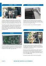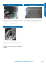
INDOOR UNIT CONTROLS and COMPONENTS
PAGE 18
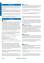
DIP Switch Settings
The PCB has a set of DIP switches
●
that must be set when
replacing the PCB.
The replacement PCB is shipped with all switches set to the
●
OFF position.
Switch settings:
J5 Selects remote code A or B. Normally set to connection
state for code A operation.
If two indoor units are used in the same area and the user
wishes to control them separately, switch J5 of the second
unit is set to the disconnected state for code B operation.
The wireless remote for the second unit is also set to code B.
J6 Selects room card able or disable. Normally set to
Set to
when used in conjunction with a room card interface utilized
in hotel rooms.
SW-1 and SW-2 Selects EEPROM codes 23, 26, 33 and 35.
Set to identify the tonnage of the unit.
Settings:
9K
(23)
SW
9K
(23)
SW
9K
(23)
SW-1
OFF
SW-2
OFF
-3
OFF
SW-4
OFF
-3
OFF
SW-4
OFF
-3
OFF
SW-4
OFF
12K
(26)
SW-1
OFF
SW-2
ON
12K
(26)
SW-3
OFF
SW-4
ON
12K
(26)
SW-3
OFF
SW-4
ON
12K
(26)
SW-3
OFF
SW-4
ON
12K
(26)
SW-3
OFF
SW-4
ON
12K
(26)
SW-3
OFF
SW-4
ON
18K
(33)
SW-1
ON
18K
(33)
SW-3
ON
18K
(33)
SW-3
ON
18K
(33)
SW-3
ON
SW-2
OFF
-4
OFF
DIP Switch
connection state.
the disconnected state
Содержание AW09EH2VHD
Страница 2: ... This page intentionally left blank ...
Страница 4: ...Failure to follow any CAUTION may in some cases result in grave consequences ...
Страница 6: ...PAGE 6 ...
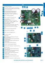
Страница 9: ...5VDC and 15VDC pulsing communication connection between the PCB and the IPM ...
Страница 10: ......
Страница 11: ......
Страница 12: ......
Страница 13: ......
Страница 14: ......
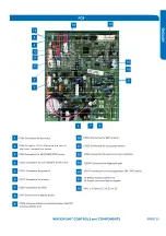
Страница 15: ...Connector for coil temperature sensor and room temperature sensor ...
Страница 17: ......
Страница 19: ......
Страница 22: ......
Страница 23: ......
Страница 26: ...PAGE 32 ...
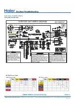
Страница 50: ...Error Code E7 LED1 15 Flash Wiring Diagram Reference PAGE 50 ERROR CODES and Troubleshooting ...
Страница 57: ...PAGE 57 Ambient Defrost and Pipe Sensor Tables Discharge Sensor Tables ...

