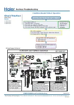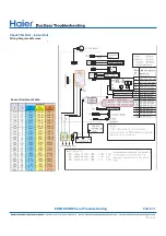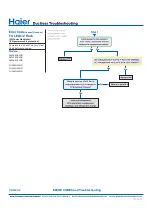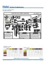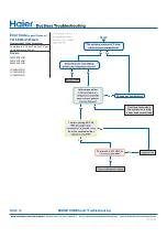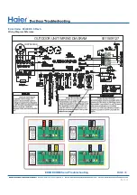
Check This First Outdoor Unit .............................................................................................................................................................29
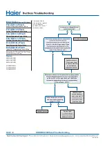
Check This First Indoor Unit ................................................................................................................................................................30
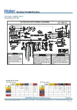
Check This First - Indoor Unit
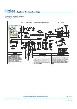
Wiring Diagram Reference....................................................................................................................................................................31
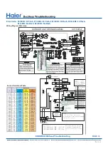
Error Code (Indoor/Outdoor)
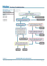
F1/LED1: 2 Flash IPM Power Module Failure
(IPM power module protection)............................................................................................................................................................32
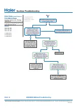
Error Code: F1/LED1: 2 Flash...............................................................................................................................................................33
Wiring Diagram Reference
Error Code (Indoor/Outdoor)
F2/LED1: 24 Flash Overcurrent of the Compressor................................................................................
●
...........................................34
Error Code: F2/LED1: 24 Flash
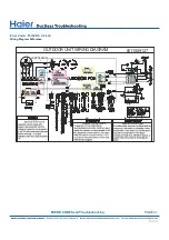
Wiring Diagram Reference....................................................................................................................................................................35
Error Code (Indoor/Outdoor)
F3/LED1: 4 Flash Communication Fault Between IPM and
Outdoor PCB..........................................................................................................................................................................................36
Error Code: F3/LED1: 4 Flash
Wiring Diagram Reference....................................................................................................................................................................37
Error Code (Indoor/Outdoor)
●
F4/LED1: 8 Flash Overheat Protection For Discharge
Temperature..........................................................................................................................................................................................38
Error Code: F4/LED1: 8 Flash
Wiring Diagram Reference....................................................................................................................................................................39
Error Codes (Indoor/Outdoor)
F6/LED1: 12 Flash Ambient Temperature Sensor Failure
F7/LED1: 11 Flash Suction Temperature Sensor Failure
F21/LED1: 10 Flash Defrost Temperature Sensor Failure
F25/LED1: 13 Flash Discharge Temperature Sensor Failure
E1/LED1: No Flash Room Temperature Sensor Failure
E2/LED1: No Flash Indoor Coil Temperature Sensor Failure.............................................................................................................40
Error Code: F6/LED1: 12 Flash, F7/LED1: 11 Flash, F21/LED1: 10 Flash, F25/LED1: 13 Flash,
E1/LED1: No Flash, E2/LED1: No Flash
Wiring Diagram Reference....................................................................................................................................................................41
Error Code (Indoor/Outdoor)
●
F8/LED1: 9 Flash Outdoor DC Fan Motor Fault...................................................................................................................................42
Error Code: F8/LED1: 9 Flash
Wiring Diagram Reference....................................................................................................................................................................43
Error Code (Indoor/Outdoor)
F11/LED1: 18 Flash Loss of Compressor Synchronization..........................................................................
●
.......................................44
Error Code: F11/LED1: 18 Flash
●
Wiring Diagram Reference.....................................................................................................................................................................45
Error Code (Indoor/Outdoor)
F12/LED1: 1 Flash EEPROM Error
Complete the “Check This First” Flow..................................................................................................................................................46
Error Code (Indoor/Outdoor)
E5/LED1: 22 Flash..............................................................................................................
.....................................................................47
Error Code: E5/LED1: 22 Flash
Wiring Diagram Reference....................................................................................................................................................................48
Error Code (Indoor/Outdoor)
E7/LED1: 15 Flash ID and OD Loss of Communication......................................................................................................................49
Error Code: E7/LED1: 15 Flash
Wiring Diagram Reference................................................................................................... ................................................................50
Error Code (Indoor)
E14 Indoor Fan Motor Failure............................................................................................... ................................................................52
Error Code: E14................................................................................................................
.........................................................................53
Checking System Components............................................................................................................................................................54
PAGE 28
ERROR CODES and Troubleshooting
Содержание AW09EH2VHD
Страница 2: ... This page intentionally left blank ...
Страница 4: ...Failure to follow any CAUTION may in some cases result in grave consequences ...
Страница 6: ...PAGE 6 ...
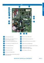
Страница 9: ...5VDC and 15VDC pulsing communication connection between the PCB and the IPM ...
Страница 10: ......
Страница 11: ......
Страница 12: ......
Страница 13: ......
Страница 14: ......
Страница 15: ...Connector for coil temperature sensor and room temperature sensor ...
Страница 17: ......
Страница 19: ......
Страница 22: ......
Страница 23: ......
Страница 26: ...PAGE 32 ...
Страница 50: ...Error Code E7 LED1 15 Flash Wiring Diagram Reference PAGE 50 ERROR CODES and Troubleshooting ...
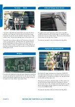
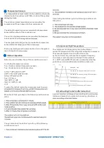
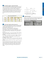
Страница 57: ...PAGE 57 Ambient Defrost and Pipe Sensor Tables Discharge Sensor Tables ...

