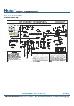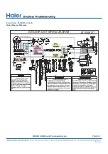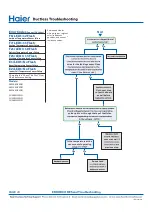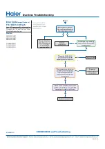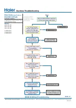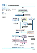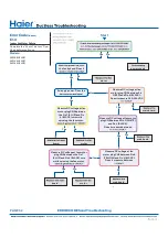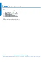
Indoor PCB OK
●
Yes
No
Yes
Yes
No
No
Is the Indoor PCB LED
Does the voltage
between L and C at
Is the voltage from
L to C at indoor unit
between 0~80VAC
Is the Indoor PCB LED
pattern repeatedly
Fault is with
outdoor PCB
motor
●
There is 230 VAC
AC-L OUT & AC-N
OUT (CN9 & CN8)
There is less than 5 VDC at
CN22 (module power) and
The voltage between
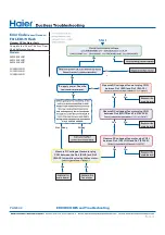
Go to outdoor PCB
No
Yes
Yes
Yes
Yes
Yes
Yes
Yes
No
No
Yes
Yes
No
No
No
LED2 (upper left) is lighted
fan motor at CN21. LED1
The display is
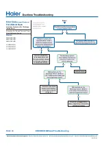
Error Code
(Indoor/Outdoor)
E7/LED1: 15 Flash
ID and OD Loss of Communication
Complete the “Check This First” Flow
Chart for both ID and OD units before
continuing.
Models:
AW09EH2VHD
AW12EH2VHD
AW18EH2VHD
1U09EH2VHD
1U12EH2VHD
1U18EH2VHD
PAGE 49
ERROR CODES and Troubleshooting
Содержание AW09EH2VHD
Страница 2: ... This page intentionally left blank ...
Страница 4: ...Failure to follow any CAUTION may in some cases result in grave consequences ...
Страница 6: ...PAGE 6 ...
Страница 9: ...5VDC and 15VDC pulsing communication connection between the PCB and the IPM ...
Страница 10: ......
Страница 11: ......
Страница 12: ......
Страница 13: ......
Страница 14: ......
Страница 15: ...Connector for coil temperature sensor and room temperature sensor ...
Страница 17: ......
Страница 19: ......
Страница 22: ......
Страница 23: ......
Страница 26: ...PAGE 32 ...
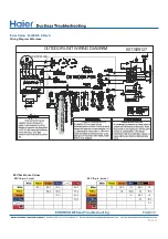
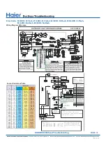
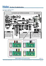
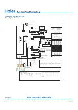
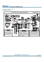
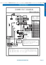
Страница 50: ...Error Code E7 LED1 15 Flash Wiring Diagram Reference PAGE 50 ERROR CODES and Troubleshooting ...
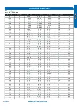
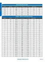
Страница 57: ...PAGE 57 Ambient Defrost and Pipe Sensor Tables Discharge Sensor Tables ...

