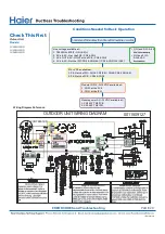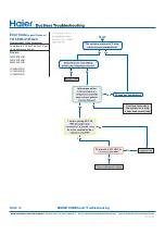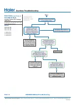
SEQUENCE OF OPERATION
PAGE 24
Tempe
T
T
rature Sensors
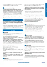
Defrost cycle will initiate if any of three conditions are met:
Te = Defrost temperature sensor
Tao = Outdoor ambient temperature sensor
Tes = Condensation point temperature
Tes = C X Tao-a
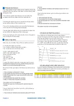
To enter the defrost mode, the compressor must have acc-
When the defrost cycle begins, the following conditions take
place:
The system will exit the defrost cycle if any of the following
conditions are met:
Upon exiting the defrost cycle, the following conditions will
take place:
Protection Functions
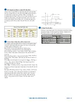
1. Compressor High Temperature
The compressor discharge pipe sensor (exhaust temp)
senses the temperature of the refrigerant exiting the compressor
The sensed temperature received from the sensor
by the control circuitry will cause the compressor fr
ff equency
to increase or decrease (see chart below If a temperature
of >= 23
f
°F is sensed fo
ff
seconds, an exhaust overheating
protection error code will be indicated at the outdoor unit
stop
Decreasing the frequency rapidly (1HZ/1second)
TTC
(°F)
°F
212
°F
°F
°F
°F
Decreasing the frequency slowly (1HZ
conds)
The frequency doesn’t change
Increasing the frequency (1HZ
conds)
Increasing the frequency (1HZ/1second)
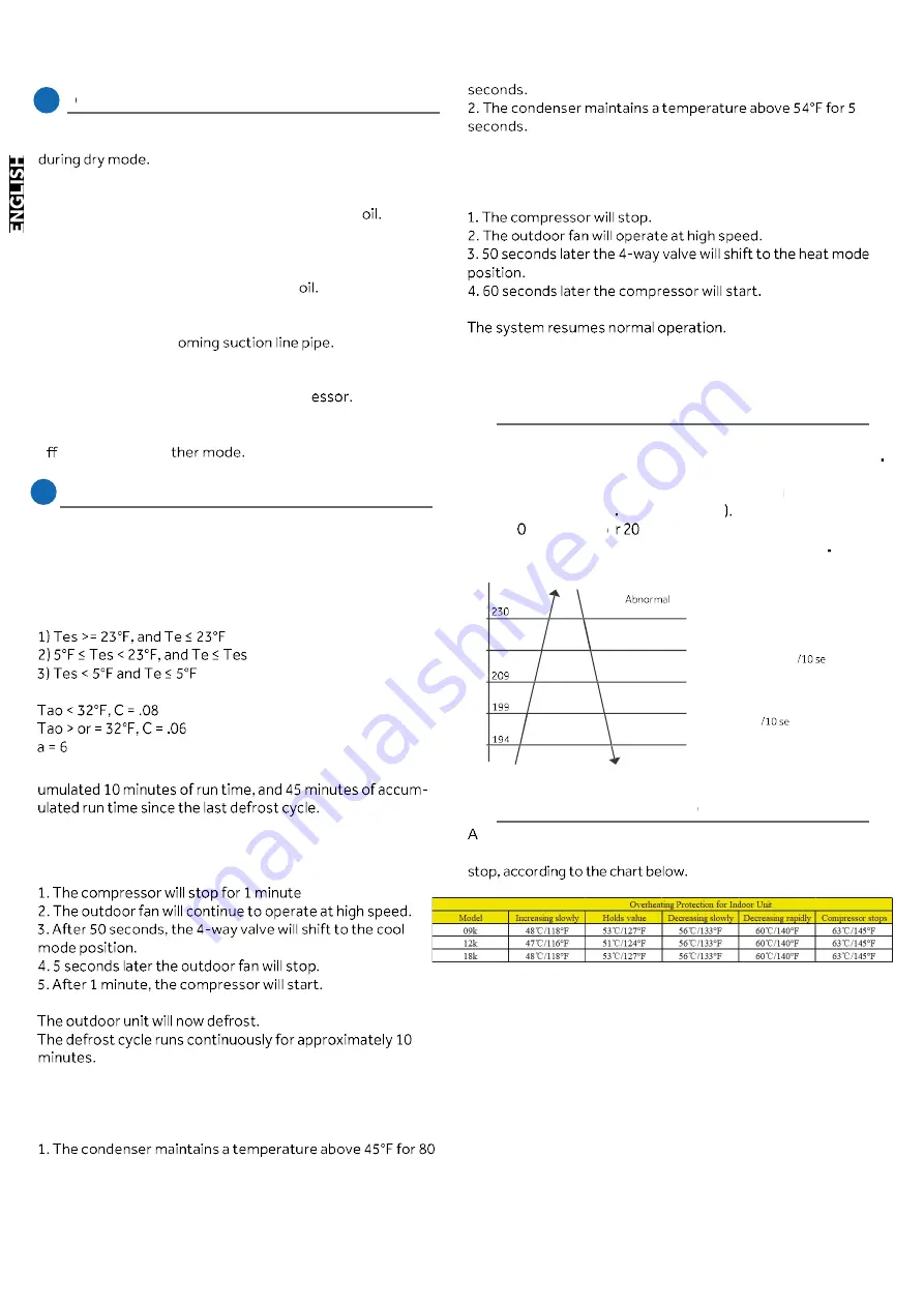
2. Overheating Protection for Indoor Unit
ff
sensor monitors coil temperature in both heating and cooling
modes, and causes the compressor to speed up, slow down, or
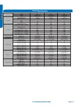
Four temperature sensors located in the outdoor unit provide
information to the outdoor unit PCB for control of the system
The outdoor ambient temperature sensor provides the
temperature of the air drawn into the condenser c
The defrost temperature sensor provides the temperature
sensed at the output of the condenser c
The suction line temperature sensor provides the tempera-
ture sensed at the inc
The compressor discharge sensor provides the temperature
sensed at the discharge pipe of the compr
To stop dry mode, press the power button to turn the system
o , or change to ano
Defrost Operation
Содержание AW09EH2VHD
Страница 2: ... This page intentionally left blank ...
Страница 4: ...Failure to follow any CAUTION may in some cases result in grave consequences ...
Страница 6: ...PAGE 6 ...
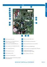
Страница 9: ...5VDC and 15VDC pulsing communication connection between the PCB and the IPM ...
Страница 10: ......
Страница 11: ......
Страница 12: ......
Страница 13: ......
Страница 14: ......
Страница 15: ...Connector for coil temperature sensor and room temperature sensor ...
Страница 17: ......
Страница 19: ......
Страница 22: ......
Страница 23: ......
Страница 26: ...PAGE 32 ...
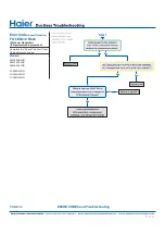
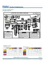
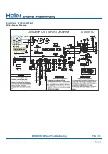
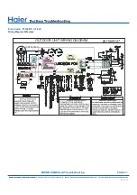
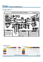
Страница 50: ...Error Code E7 LED1 15 Flash Wiring Diagram Reference PAGE 50 ERROR CODES and Troubleshooting ...
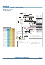
Страница 57: ...PAGE 57 Ambient Defrost and Pipe Sensor Tables Discharge Sensor Tables ...


