background image

Installation Manual 
H3C SecPath F1000-E Firewall 

Chapter 6  Maintaining Software


6-26 

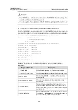
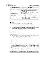
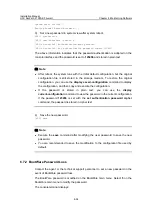
Table 6-10 

Description on the information displayed when you upgrade and backup an 

application file on the firewall 

Display information 

Description 

[ftp]get main.bin main.bin 

Download the file used for upgrade


cfa0:/main.bin has been existing. 
Overwrite it? [Y/N]:y 

The system prompts whether to 
overwrite the existing file.


FTP: 10867848 byte(s) received in 
472.515 second(s), 23.00K byte(s)/sec 

Download and upgrade of the 
application file is finished.


[ftp]put main.bin main.bin 

Upload the file from the firewall to the 
server.


FTP: 4722 byte(s) sent in 0.074 
second(s), 63.00Kbyte(s)/sec 

Upload and backup of the application file 
is finished.


[ftp]quit 

Quit FTP client view.


221 Service closing control connection 

Close the service control connection. 


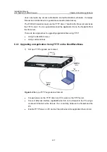
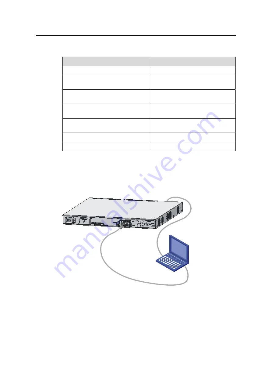
II. Firewall servers as the FTP server; PC serves as the FTP client 

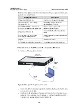
1) 

Set up an FTP upgrade environment. 

PC

(FTP client)

Console 

cable

Ethernet 

cable

F1000-E

(FTP server)


Figure 6-11 

Set up an FTP upgrade environment 

z


Connect the Ethernet interface GigabitEthernet 0/0 on the firewall to the PC using 

a crossover Ethernet cable.  

z


Configure the IP addresses of the server and client to be on the same network 

segment. In this example, the IP address of interface GigabitEthernet 0/0 is 

192.168.80.10, and that of the PC is 192.168.80.200. 

Содержание SecPath F1000-E

Страница 1: ...H3C SecPath F1000 E Firewall Installation Manual Hangzhou H3C Technologies Co Ltd http www h3c com Manual Version T2 080499 20071221 C 1 00...

Страница 2: ...nnoVision and HUASAN are trademarks of Hangzhou H3C Technologies Co Ltd All other trademarks that may be mentioned in this manual are the property of their respective owners Notice The information in...

Страница 3: ...t specifications as well as the features and applications of the H3C SecPath F1000 E Firewall 2 Interface Modules Describes the interface cards and interface modules supported by the H3C SecPath F1000...

Страница 4: ...Convention Description Boldface Window names button names field names and menu items are in Boldface For example the New User window appears click OK Multi level menus are separated by angle brackets...

Страница 5: ...es 1 4 1 3 2 Dimensions and Weight 1 5 1 3 3 Fixed Interfaces and Slots 1 5 1 3 4 Power Input 1 5 1 3 5 Operating Environment 1 6 1 4 Components 1 6 1 4 1 Processor and Storages 1 6 1 4 2 Panel LEDs 1...

Страница 6: ...mation Protocol RIP Open Shortest Path First OSPF and Border Gateway Protocol BGP Employing a high performance multi core processor the F1000 E supports a maximum of 20 GE interfaces providing a good...

Страница 7: ...of connection oriented application layer protocols to maintain the state information of each connection and dynamically decides whether to permit or drop a packet z P2P flow control The F1000 E uses...

Страница 8: ...100 VAC to 240 VAC 50 Hz or 60 Hz 2 5 A 2 AC power switch ON OFF 3 RPS socket RPS 4 CF card slot CF CARD 5 CF card LED CF 6 RPS LED RPS 7 Slot 2 LED SLOT2 8 System LED SYS 9 Slot 1 LED SLOT1 10 AC po...

Страница 9: ...ps electrical Ethernet interface 3 9 1000 Mbps optical Ethernet interface 3 10 HIM slot 2 11 HIM slot 1 12 1000 Mbps optical Ethernet interface 2 13 10 100 1000 Mbps electrical Ethernet interface 2 14...

Страница 10: ...default USB 0 Type A connector operating in the host mode USB interfaces 2 USB 1 Type B connector operating in the device mode Combo interfaces 4 z Four 10 100 1000 Mbps electrical Ethernet interface...

Страница 11: ...aining space for BootWare backup and important system parameters III Memory modules The default memory size of the F1000 E is 1 GB and the maximum memory size is 2 GB The F1000 E provides two memory m...

Страница 12: ...se provided other manufacturers 2 CF card and slot 1 2 3 1 Eject button 2 CF card slot 3 CF card LED CF Figure 1 3 CF card and slot 3 CF card LED For the description of the CF card LED see Table 1 6 C...

Страница 13: ...lot 1 or the interface module is faulty SLOT1 Green ON An interface module is in slot 1 and operates normally OFF No interface module is in slot 2 or the interface module is faulty SLOT2 Green ON An i...

Страница 14: ...the device in this state II Rear Panel LEDs 1 2 3 4 5 6 7 8 1 10 100 1000 Mbps electrical Ethernet interface LED GE0 2 10 100 1000 Mbps electrical Ethernet interface LED GE1 3 1000 Mbps optical Ether...

Страница 15: ...e SFP port 1 4 3 Fixed Interfaces Table 1 8 Fixed interfaces Fixed interface Specification Console 1 AUX 1 USB0 Type A connector operating in the host mode USB interfaces 2 USB1 Type B connector opera...

Страница 16: ...chronous EIA TIA 232 Baud rate 9600 bps to 115200 bps 9600 bps default Transmission Distance 15 m 49 2 ft Services Connection to an ASCII terminal Connection to the serial interface of a local PC to r...

Страница 17: ...ging configuration maintenance and management In the event that the console port fails the AUX port can be connected to a terminal as a backup port of the console port For details refer to section 8 4...

Страница 18: ...8 8 CTS Note For the connection of the AUX cable refer to section 4 10 2 Connecting the AUX Port to a Modem in Chapter 4 Installing the Firewall III GE combo interfaces 1 Introduction The F1000 E prov...

Страница 19: ...respectively z The optical Ethernet interface supports a rate of 1000 Mbps in full duplex mode The optical Ethernet interface LEDs are in the middle of the four GE combo interfaces and use separate L...

Страница 20: ...lectrical Ethernet interface Item Specification Connector RJ 45 Interface Autosensing When working in the forced mode Ethernet does not support MDI MDI X autosensing Frame format Ethernet_II Ethernet_...

Страница 21: ...1550 nm 1550 nm Fiber type 62 5 125 m multimod e fiber 9 125 m single mod e fiber 9 125 m single mo de fiber 9 125 m single mod e fiber 9 125 m single mo de fiber Maximum transmission distance 0 55 k...

Страница 22: ...round plug in optical fiber connector z MT RJ square optical transceiver connector Currently the optical Ethernet interfaces of the F1000 E support LC connectors only Figure 1 10 LC connector Note z B...

Страница 23: ...t both ends of a crossover cable wires are crimped in the RJ 45 connectors in different sequences A crossover cable is used to connect a terminal for example a PC or a firewall to another terminal You...

Страница 24: ...ical Ethernet interface to an Ethernet You can select proper fibers for the installed 1000Base FX SFP modules Since the optical interfaces on these SFP modules use LC optical connectors you must use f...

Страница 25: ...ms configuration files and security VPN certificates to establish secure VPN connections and secure the delivery of firewall configuration files In addition USB interfaces provide a backup CF card mec...

Страница 26: ...tem Specification Rated voltage range 100 VAC to 240 VAC 50 Hz or 60 Hz Maximum input current 2 5 A Maximum power 150 W 1 4 7 Clock The F1000 E firewall is designed with a clock module that provides t...

Страница 27: ...s within 10 ms and starts to supply power to the firewall The F1000 E provides two power inputs AC power input and RPS input They can guarantee the firewall to continue working when one power supply f...

Страница 28: ...500 VAC to 220 VAC Note For the installation of the power lightning arrester refer to section 4 7 Installing a Power Lightning Arrester Optional in Chapter 4 Installing the Firewall 1 4 11 Signal Lig...

Страница 29: ...nstalling the Firewall 1 4 12 System Software The F1000 E operates on Comware V5 the core software platform of H3C By supporting abundant security features such as virtual firewall attack prevention l...

Страница 30: ...F1000 E Firewall Table of Contents i Table of Contents Chapter 2 Interface Modules 2 1 2 1 4GBE 8GBE 2 1 2 2 Arranging Slots and Numbering Interfaces 2 3 2 2 1 Slot Arrangement 2 3 2 2 2 Interface Nu...

Страница 31: ...ace is provided with a bi color LED indicating the running status of the interface 8GBE is connected to the processor through a 10 Gbps high speed bus and can provide all the high performance Layer 3...

Страница 32: ...nk is present Flashing green Data is being received or transmitted at a rate of 1000 Mbps Solid yellow A 10 100 Mbps link is present Flashing yellow Data is being received or transmitted at a rate of...

Страница 33: ...er Ethernet cable Figure 2 3 Ethernet cable Note For the connection of a 4GBE 8GBE interface cable refer to section 4 10 4 I Connecting a 2GBE 4GBE 8GBE interface module cable in Chapter 4 Installing...

Страница 34: ...terfaces on a module share the same slot number X 3 For each type of interfaces Y starts from 0 and is incremented from left to right on the interface module 2 2 3 Examples 1 The fixed optical electri...

Страница 35: ...Discharge Prevention 3 3 3 1 5 Electromagnetic Interference Prevention 3 4 3 1 6 Lightning Protection 3 5 3 1 7 Workbench Requirements 3 5 3 1 8 Cabinet Mounting Requirements 3 5 3 2 Safety Precautio...

Страница 36: ...rough the exhaust vents on the right Figure 3 1 Ventilation method for the F1000 E Make sure that There is a minimum clearance of 10 cm 3 9 in around the air intake and the air exhaust for heat dissip...

Страница 37: ...is may result in static adsorption which causes poor contact between metal connectors or joints The poor contact may not only shorten the service life of the firewall but also bring about communicatio...

Страница 38: ...lectrostatic discharge ESD Make sure that the firewall and the floor are well grounded Take dust proof measures for the equipment room Maintain the humidity and temperature at a proper level respectiv...

Страница 39: ...ive wrist strap is shipped with the F1000 E and you have to supply one by yourself 3 1 5 Electromagnetic Interference Prevention All possible interference sources external or internal affect the firew...

Страница 40: ...he power supply to enhance the lightning protection capability of the power supply To enhance the lightning protection capability install a special lightning arrester at the input end of outdoor signa...

Страница 41: ...ssis and installation tools away from walk area Keep the firewall far away from a moist area and heat sources Unplug all external cables before moving the chassis 3 2 3 Electricity Safety Locate the e...

Страница 42: ...150 mm and P3 250 mm Flat blade screwdrivers P4 75 mm Screws of various sizes Meters and devices such as hub configuration terminal optional modules multimeter Optional cables ESD preventive gloves ES...

Страница 43: ...ith the face upward or put it into an antistatic bag Touch only the edges instead of electronic components when observing or moving a removed memory module CF card or HIM EMI prevention Take effective...

Страница 44: ...ventilation system The rack is sturdy enough to support the weight of the firewall and installation accessories The size of the cabinet is appropriate for the firewall The front and rear of the cabin...

Страница 45: ...ning Arrester Optional 4 7 4 6 1 Tools 4 8 4 6 2 Installation Procedure 4 8 4 6 3 Precautions 4 9 4 7 Installing a Power Lightning Arrester Lightning Protection Busbar Optional 4 9 4 8 Selecting and I...

Страница 46: ...hapter 3 Preparing for Installation are satisfied 4 2 Installation Flowchart Connect the firewall to the LAN Connect the firewall to a configuration terminal End Verify the installation Connect the fi...

Страница 47: ...installation make sure z The length and width of the workbench are larger than the distance between the feet of the firewall See Table 4 1 for the dimensions of the firewall Table 4 1 Dimensions of th...

Страница 48: ...et Installation Guide II Installing rack mounting brackets onto the firewall 1 Structure of the rack mounting brackets 1 2 3 4 1 Left front rack mounting bracket 2 Right front rack mounting bracket 3...

Страница 49: ...left and right sides of the firewall for fixing the firewall to the rear rack mounting brackets as shown in Figure 4 4 3 Put the firewall on the rack making sure it is seated on the left and right re...

Страница 50: ...nnect the PGND cable when installing or using the firewall The power input end of the F1000 E is equipped with a noise filter The neutral ground of the power input end is directly connected to the cha...

Страница 51: ...ched with the OT terminal of the PGND cable into the grounding screw hole with a screwdriver 4 Connect the other end of the PGND cable to the ground Generally the cabinets installed in equipment rooms...

Страница 52: ...causes damage to the firewall 4 6 Installing a Port Lightning Arrester Optional Note z Only 10 100 Mbps RJ 45 Ethernet ports need to be equipped with port lightning arresters z No port lightning arres...

Страница 53: ...he firewall 3 Use the multimeter to check the connection between the grounding cable of the port lightning arrester and the grounding screw of the firewall 4 Follow the instructions to connect the por...

Страница 54: ...u need to check with a multimeter after connection z The installed port lightning arresters are not sufficient When more than one outdoor Ethernet cable is connected to the firewall you need to instal...

Страница 55: ...whether the grounding cable is not well connected or the live and zero wires are connected reversely When the red LED is ON use a multimeter to examine the polarity at the multi purpose socket of the...

Страница 56: ...lightning arrester you need to consider such performance indexes of the lightning arrester as lightning protection bandwidth transmission loss and port type The F1000 E supports three types of signal...

Страница 57: ...ecifications for the AC power socket see Table 4 2 Table 4 2 Technical specifications for the AC power socket of the F1000 E Item Specification AC power socket 100 VAC to 240 VAC 4 9 2 Connecting the...

Страница 58: ...PWR LED on the front panel of the firewall For the status of the power LED see Table 4 3 Table 4 3 Status of the power LED Color Status OFF No power supply is available ON The power module works abnor...

Страница 59: ...panel 4 Shake the blank panel slightly and then take it off Now you can see the RPS socket Figure 4 14 RPS socket 5 Plug the RPS power cable into the RPS socket on the firewall 6 Turn the screws on th...

Страница 60: ...er socket on the firewall 6 RPS power socket Figure 4 16 Connect the RPS DC power cable to the RPS power output port 8 Turn on the power switch on the firewall and the RPS power switch 9 Check the sta...

Страница 61: ...ection and power on the firewall The configuration terminal displays the startup banner of the firewall if the connection is correct For details refer to section 5 2 Firewall Power on in Chapter 5 Sta...

Страница 62: ...rt on the firewall 2 Plug the DB 25 male or DB 9 male connector into the serial port on the analog modem 1 3 2 5 4 1 AUX port 2 RJ 45 connector 3 AUX cable 4 Modem 5 DB 25 male or DB 9 male connector...

Страница 63: ...t Flashing green Data is being transmitted received at 1000 Mbps Solid yellow A 10 100 Mbps link is present GE0 to GE3 yellow green Flashing yellow Data is being transmitted received at 10 100 Mbps II...

Страница 64: ...d of one fiber cable into the Rx port of the firewall and the LC connector at the other end into the Tx port of the peer device Plug the LC connector at one end of another fiber cable into the Tx port...

Страница 65: ...a 4GBE 8GBE interface module cable You can use a straight through cable or crossover cable to connect a 2GBE 4GBE 8GBE interface module cable Follow these steps to connect a 2GBE 4GBE 8GBE interface...

Страница 66: ...of the LED see Table 2 1 in Chapter 2 Interface Modules 4 11 Verifying Installation Each time you power on the firewall during installation you must verify that z There is enough space around the fire...

Страница 67: ...1 5 1 2 Setting the Parameters for the Console Terminal 5 1 5 2 Firewall Power On 5 4 5 2 1 Checklist for Firewall Power On 5 4 5 2 2 Powering On the Firewall 5 5 5 2 3 Checklist Operations after Fir...

Страница 68: ...uration terminal refer to section 4 10 1 Connecting the Console Cable in Chapter 4 Installing the Firewall 5 1 2 Setting the Parameters for the Console Terminal 1 Create a connection Select Start Prog...

Страница 69: ...nfiguration connection 3 Set serial port parameters Set the properties of the serial port in the COM1 Properties dialog box as shown in Figure 5 3 Table 5 1 Set serial port parameters Item Value Bits...

Страница 70: ...0 E Firewall Chapter 5 Starting and Configuring the Firewall 5 3 Figure 5 3 Set serial port parameters 4 Click OK after setting the serial port parameters to enter the HyperTerminal window as shown be...

Страница 71: ...ick OK to return to the HyperTerminal window Figure 5 5 Set the terminal type 5 2 Firewall Power On 5 2 1 Checklist for Firewall Power On Before powering on the firewall check that z The power cord an...

Страница 72: ...the front panel are normal The following table describes normal LED states after the firewall is powered on Table 5 2 Normal LED states after firewall power on LED State Meaning PWR green ON The powe...

Страница 73: ...ower on the firewall initializes its memory and then runs the extended BootWare The following information appears on the terminal screen Note The information displayed on the terminal may vary with di...

Страница 74: ...ENTER to get started Press Enter The screen will display H3C This prompt indicates that the firewall has entered user view and is ready to configure 5 4 Configuration Fundamentals In general the confi...

Страница 75: ...to perform local configuration through the console port z Allows you to perform the local or remote configuration and directly log in to and manage other firewalls by using the telnet command z Provi...

Страница 76: ...he F1000 E Connect the Ethernet interface GigabitEthernet 0 0 of the F1000 E to a PC using a crossover network cable For the connection of the console cable refer to section 4 10 3 Connecting Ethernet...

Страница 77: ...3 4 Upgrading BootWare 6 15 6 4 Upgrading an Application Using TFTP 6 16 6 4 1 Upgrading an Application Using TFTP on the BootWare Menu 6 17 6 4 2 Upgrading an Application Using TFTP Through Command...

Страница 78: ...Installation Manual H3C SecPath F1000 E Firewall Table of Contents ii 6 9 2 Software Upgrade Configuration Example 6 39...

Страница 79: ...d the CF card are unavailable z Extended segment of BootWare provides abundant human computer interaction HCI functions and available network interfaces and CF card and can be used to upgrade the appl...

Страница 80: ...the type of the secure application file or change other types of files to the secure application file You can only download it using the BootWare menu z There is only one file of the same type M B or...

Страница 81: ...g commands after the application boots You cannot modify the type of the default configuration file but you can modify the file type of type M B and N configuration files using commands after the appl...

Страница 82: ...separately The system automatically upgrades the BootWare program to the latest version if the current BootWare version is found to be inconsistent with the BootWare version contained in the host appl...

Страница 83: ...different BootWare versions System start booting Booting Normal Extend BootWare H3C SecPath F1000 E BootWare Version 1 12 Copyright c 2004 2007 Hangzhou H3C Technologies Co Ltd Compiled Date Jul 27 2...

Страница 84: ...when Press Ctrl B to enter extended boot menu appears The system prompts Please input BootWare password You can try up to three times to enter the BootWare password the initial password is null If yo...

Страница 85: ...em configuration ignored This operation is valid this time and you need to configure it next time 7 BootWare Operation Menu BootWare operation submenu For detailed information refer to section 6 2 5 B...

Страница 86: ...ade the backup application file 4 Update Secure Application File Upgrade the secure application file 5 Modify Serial Interface Parameter Modify serial interface parameters 0 Exit To Main Menu Return t...

Страница 87: ...l Submenu Select 4 on the BootWare main menu to enter the file control submenu where you can view the application files modify file names and delete files The system displays File CONTROL Note the ope...

Страница 88: ...tWare through Ethernet 0 Exit To Main Menu Return to the BootWare main menu 6 2 6 Storage Device Operation Submenu Select 9 on the BootWare main menu to enter the storage device operation submenu DEVI...

Страница 89: ...arts to transmit data packets When receiving a complete packet the receiving program checks the packet using the agreed method z If the check succeeds the receiving program sends an acknowledgement ch...

Страница 90: ...NTER when ready At this time the baud rate of the serial interface of the firewall is modified to 115200 bps while that of the terminal is still 9600 bps The firewall and the terminal cannot communica...

Страница 91: ...reen when the system boots or reboots 6 3 3 Upgrading an Application The application upgrade through a serial interface is implemented on the serial submenu Select 2 on the BootWare main menu to enter...

Страница 92: ...following dialog box appears Figure 6 6 Sending file dialog box After the file is downloaded the following information appears on the terminal interface Download successfully 10129792 bytes downloade...

Страница 93: ...ding speed refer to section 6 3 2 Modifying Serial Interface Parameters on page 6 11 and then select 3 on the BootWare operation submenu The system prompts BOOTWARE OPERATION SERIAL SUB MENU 1 Update...

Страница 94: ...while upgrading the application z The file name size and path in the above figures may vary Check the current BootWare and application versions before upgrading them z If you upgraded the extended seg...

Страница 95: ...o from the file server There are two approaches to upgrading application files using TFTP z Using the BootWare menu z Using command lines 6 4 1 Upgrading an Application Using TFTP on the BootWare Menu...

Страница 96: ...in bin Server IP Address 192 168 80 200 Local IP Address 192 168 80 10 Gateway IP Address FTP User Name FTP User Password Table 6 7 Description on the display information of setting Ethernet interface...

Страница 97: ...to the BootWare submenu where you can select 2 to upgrade the main application file Loading done 10129712 bytes downloaded Updating File cfa0 main bin Update Success 4 After the upgrade is finished se...

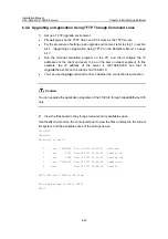
Страница 98: ...the server is 192 168 80 200 and that of GigabitEthernet 0 0 on the client is 192 168 80 10 z You can use the ping command to check whether the connection is successful Caution You can upgrade the app...

Страница 99: ...wait File will be transferred in binary mode Downloading file from remote TFTP server please wait TFTP 10867848 bytes received in 512 615 second s File downloaded successfully Note z When you downloa...

Страница 100: ...nfiguration file using the same method as backing up an application file 6 5 Upgrading an Application Using FTP When the application file is large you can also upgrade it using FTP to save upgrade and...

Страница 101: ...ver Ethernet cable z Enable FTP Server on PC and set the path where the application file is stored z Set the FTP username and password Caution z The FTP server software is not included in the F1000 E...

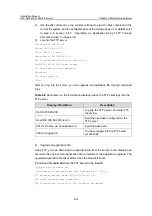
Страница 102: ...iption on the information displayed when the FTP client logs into the FTP server Display information Description ftp 192 168 80 200 Log into the FTP server and enter FTP client view User 192 168 80 20...

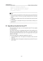
Страница 103: ...ion file to the firewall and the modification takes effect after the firewall reboots 5 Back up an application file Using FTP you can backup an application file by uploading it to the server Upload fi...

Страница 104: ...m the firewall to the server FTP 4722 byte s sent in 0 074 second s 63 00Kbyte s sec Upload and backup of the application file is finished ftp quit Quit FTP client view 221 Service closing control con...

Страница 105: ...a local user and enter user view service type ftp Set the service type that can be used locally to FTP password simple 123456 Configure the user password level 3 Set the user level to 3 Note z The FTP...

Страница 106: ...n 192 168 80 10 In FTP client view log into the IPv4 FTP server User 192 168 80 10 none Input the username configured on the FTP server 331 Password required for guest Input the password 230 User logg...

Страница 107: ...from the server to the client Download file main bin from the FTP server to the PC and save it as main_bac bin ftp get main bin main_bac bin 200 Port command okay 150 Opening BINARY mode data connect...

Страница 108: ...ion File type 3 Delete File 0 Exit To Main Menu Enter your choice 0 3 6 6 1 Displaying All Files I Displaying all files on the BootWare menu Select 1 on the file control submenu and the system display...

Страница 109: ...ote For details about the dir command refer to H3C SecPath Series Security Products User Manual 6 6 2 Setting the Application File Type I Setting application file type on the BootWare menu You can mod...

Страница 110: ...ication file for the next startup If there was an M type of application file the type of that file was automatically changed to N Note For details about the boot loader command refer to H3C SecPath Se...

Страница 111: ...n H3C undelete startup cfg Undelete cfa0 startup cfg Y N y Undeleted file cfa0 startup cfg Note For details about the delete and undelete commands refer to H3C SecPath Series Security Products User Ma...

Страница 112: ...can use the display saved configuration command to display the configuration and then copy and execute the configuration z If the password is stored in plain text you can use the display current conf...

Страница 113: ...ssword again The system displays the following information indicating success of setting the new password Password Set Successfully 6 7 3 Super Password Loss The super password enables you to switch b...

Страница 114: ...BootWare Operation Submenu on page 6 9 for details 6 8 1 Backing Up the Full BootWare I Backing up the full BootWare using BootWare menu options To backup a full BootWare you need to backup the basic...

Страница 115: ...Ware in the system with the BootWare stored in the Flash To restore a full BootWare you need to restore the basic segment and then the extended segment Will you restore the Basic BootWare Y N Select Y...

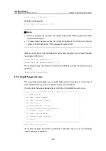
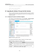
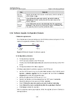
Страница 116: ...es the software 6 9 1 Configuring Parameters for Software Upgrade Upon logging in to the Web NMS interface and select System Software Upgrade from the navigation bar on the left to enter the page show...

Страница 117: ...twork diagram for software upgrade II Configuration procedure 1 Configuration prerequisites z TFTP has been enabled on the TFTP server z The file to be downloaded source bin exists under the main dire...

Страница 118: ...irewall Chapter 6 Maintaining Software 6 40 3 Verify the upgrade result Use the display boot loader command on the TFTP server to verify the software upgrade result Sysname display boot loader The fil...

Страница 119: ...7 4 7 5 2 Removing Blank Panels 7 5 7 5 3 Installing a Blank Panel 7 6 7 6 Installing and Removing an HIM 7 6 7 6 1 Installing an HIM 7 6 7 6 2 Removing an HIM 7 7 7 7 Inserting and Removing a CF Card...

Страница 120: ...l dealer or technical support engineers appointed by H3C z To avoid injuries ensure that all power sources to the firewall are disconnected before maintaining any hardware modules of the firewall z Al...

Страница 121: ...result in unavailability of firewall services by the local dealer Follow these steps to open the chassis cover 1 Power off the firewall and unplug the power cord 2 Unplug all cables from the interfac...

Страница 122: ...r about five centimeters Figure 7 3 Pull the chassis cover about five centimeters 5 Lift the end of the chassis cover and then pull the chassis cover away from the bottom part of the chassis as shown...

Страница 123: ...n 4 Memory module connector 5 Built in CF card 6 Power supply Figure 7 5 Interior structure of the F1000 E 7 5 Installing and Removing Blank Panels 7 5 1 Blank Panel Structure Installed in the positio...

Страница 124: ...w of a blank panel Figure 7 6 Structure of a blank panel 7 5 2 Removing Blank Panels Follow these steps to remove a blank panel 1 Face the rear panel of the firewall 2 Select the slot where you will i...

Страница 125: ...cedure 7 6 Installing and Removing an HIM 7 6 1 Installing an HIM Follow these steps to install an HIM 1 Power off the firewall and face the rear panel of the firewall 2 Remove the two blank panels fr...

Страница 126: ...odule if the LED goes off the interface module failed the self test 7 6 2 Removing an HIM To remove an HIM reverse the installation procedure Caution z After removing an HIM place it in an antistatic...

Страница 127: ...til it is firmly seated Figure 7 10 Insert the CF card into the slot Note If the application program for booting the firewall is stored in an external CF card make sure that the right CF card has been...

Страница 128: ...is flashing to avoid hardware damage z To protect the CF card place it into an antistatic bag 7 8 Replacing a Memory Module 7 8 1 When to Replace a Memory Module Memory modules are removable component...

Страница 129: ...Co Ltd only Otherwise anomalies might occur to the device z For specific specifications of memory modules supported by the F1000 E firewall refer to 1 4 1 Processor and Storages in Chapter 1 Product...

Страница 130: ...the F1000 E Figure 7 15 Structure of a memory module connector 7 8 4 Removing a Memory Module 1 Make sure all power supplies to the firewall are disconnected 2 Pull the latches away from the memory m...

Страница 131: ...l are disconnected 2 Align the polarization notch on the mating edge of the memory module with the polarization key in the memory module connector 3 Position the memory module so that it is perpendicu...

Страница 132: ...g Fans 8 1 8 3 Troubleshooting the Configuration System 8 2 8 3 1 No Display on the Terminal Screen 8 2 8 3 2 Illegible Characters on the Terminal Screen 8 2 8 3 3 Serial Port Response Failure 8 2 8 4...

Страница 133: ...ove the chassis cover z Check whether the power cord is properly and firmly connected z Check whether the power cord is not damaged If the cause cannot be located in the steps above and the problem pe...

Страница 134: ...e console cable is connected is not the one configured in the emulation program z Terminal settings are incorrect The required settings are as follows 9600 bits per second 8 data bits 1 stop bit no fl...

Страница 135: ...port is flow z Power off the firewall connect the RJ 45 connector of the console cable to the AUX port and then connect the DB 9 female connector to the serial port of the configuration terminal z Pow...

Страница 136: ...Trap 1 3 6 1 4 1 2011 2 23 1 12 1 16 hwBoaardTemperatureHigher frameIndex is 0 slotIndex 0 0 Jun 28 10 27 28 433 2007 H3C DEV 4 BOARD TEMP TOOHIGH Board temperature is too high on Frame 0 Slot 0 type...

Страница 137: ...lation Manual H3C SecPath F1000 E Firewall Chapter 8 Troubleshooting 8 5 z The HIM cable is correctly connected z The interface has been correctly configured and is working normally use the display co...

Отзывы: