


7-1
7
Installing modules
Slot arrangement
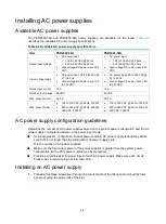
Unless otherwise stated, MPUs, interface modules, and fabric modules are collectively referred to
as "modules" in this document.
The CR19000-16 router has an MPU section, interface module section, fabric module section,
power supply section, and fan tray section.
refers to an interface module and "SFU" refers to a fabric module.
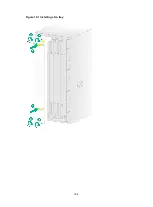
Figure 7-1 CR19000-16 router main sections
Installing MPUs
CAUTION:
•
The router supports active/standby MPU switchover. For the standby MPU to operate correctly,
make sure the active and standby MPUs are the same model.
•
If you are not to install an MPU in an MPU slot, keep the filler panel in the slot.
The router has two MPU slots. You can install one MPU, or two MPUs in 1+1 redundancy for the
router.
Содержание CR19000-16
Страница 16: ...4 3 Figure 4 3 Mounting the router in a rack...
Страница 25: ...6 8 Figure 6 6 Connecting an AC power cord using a releasable cable tie...
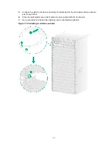
Страница 36: ...9 3 Figure 9 3 Installing a filler panel in a fabric module slot...
Страница 38: ...10 2 Figure 10 1 Installing a fan tray...
Страница 43: ...11 5 Figure 11 6 Routing signal cables...


