Instructions for Safe Selection, Installation, Use, Maintenance, Repair and
Transport
User instructions (in compliance with ATEX 94/9/EC Directive, Annex II, 1.0.6)
Unit
Part No.
Temperature Range
ATEX Certification No.
Series 2
Rechargeable
20-0108-1 -25
°
C to +55
°
C
SIRA 11ATEX2254X
Rechargeable
20-0108-L-1 -40
°
C to +55
°
C
SIRA 11ATEX2254X
Primary Cell Responder
20-0138-1
-40
°
C to +55
°
C
SIRA 11ATEX2286X
Primary Cell Pack
21-0314-1
-40
°
C to +55
°
C
SIRA 11ATEX2286X
Series 3
Rechargeable
20-0189-2
-40°C to +55°C
SIRA 15ATEX2015X
Mains Powered
20-0195-2
-40°C to +47°C
SIRA 15ATEX2047X
Primary Cell Responder
20-0194-2
-40°C to +55°C
SIRA 15ATEX2048X
Narrow Beam Primary
20-0196-2
-40°C to +55°C
SIRA 15ATEX2048X
Cell Responder
Primary Cell Pack
21-0375-1
-40°C to +55°C
SIRA 15ATEX2048X
Use in Hazardous Environments
•
Series 2 responders and primary cell packs may be used in zones
1
or
2
with flammable
gases.
•
Series 3 responders and primary cell packs may be used in zones
0
,
1
or
2
with flammable
gases.
•
All Series 2 and 3 responders and primary cell packs may be used in the presence of flammable
gases and vapours with apparatus groups
IIB
or
IIA
and with temperature classes
T1
or
T2
or
T3
or
T4.
•
The equipment is certified for use in ambient temperatures in the applicable
range shown above and should not be used outside this range.
Installation and Maintenance
•
Responders must be installed by suitably trained personnel in accordance
with the applicable code of practice (typically IEC EN 60079-14).
•
Responders must be inspected regularly by suitably trained personnel in accordance
with the applicable code of practice to ensure they are maintained in a satisfactory condition.
•
Responders are not intended to be repaired by the user. They must only be repaired or serviced
by Guidance Marine, or by an approved service representative of Guidance Marine, in accordance
with the applicable code of practice.
•
Responders do not require assembly or dismantling.
They do not contain any customer-replaceable parts, and no user adjustment is required.
Responder Overview (continued)
Responder colours:
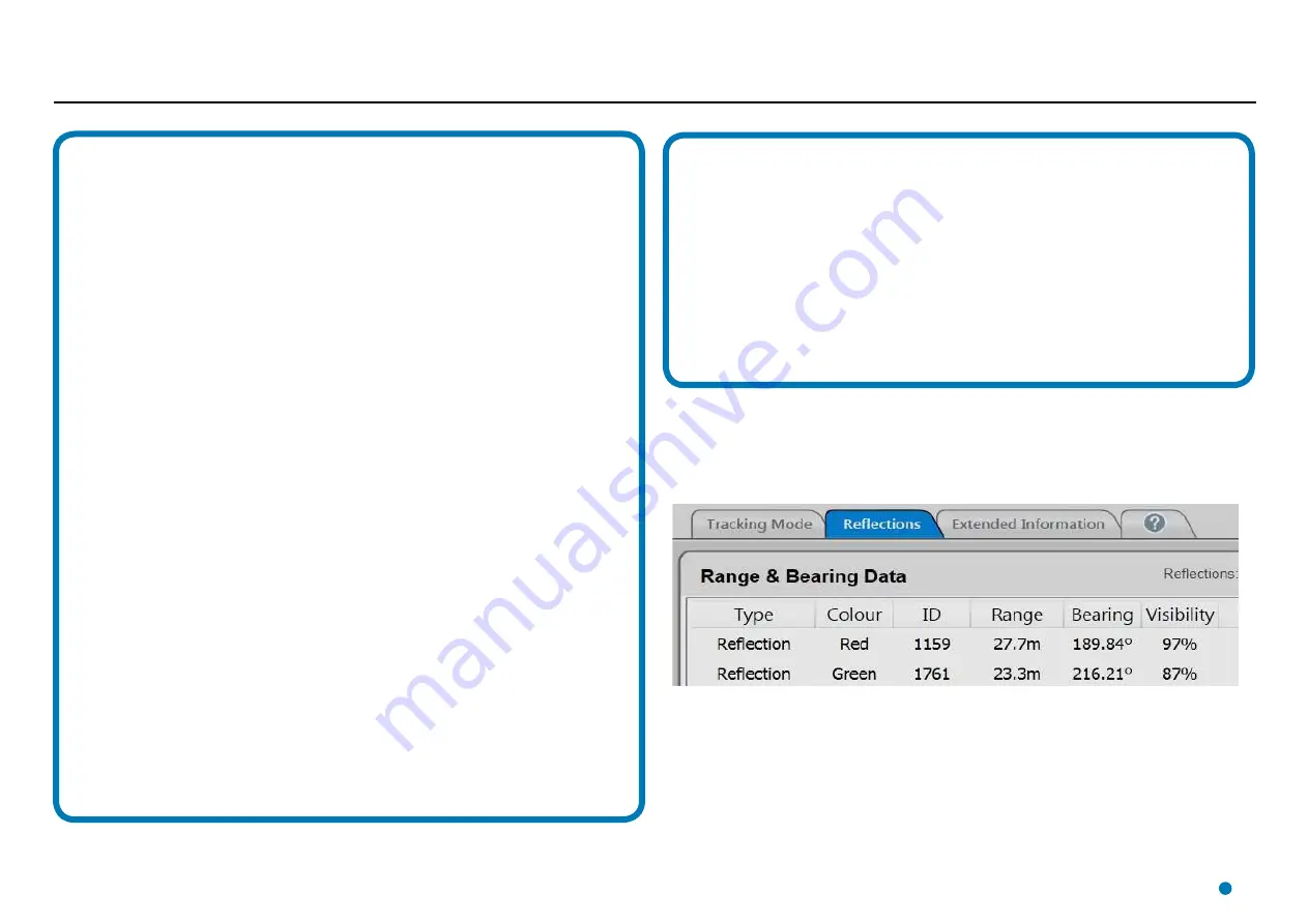
Each Series 2 or 3 Responder uses one of four different modulation frequencies. These are
characterised as colours: Red, Yellow, Green and Blue. The colour of a responder is clearly
marked on the outside of its case, and is shown next to its ID number on the Reflections and
Extended Information panes of the Dashboard.
This scheme makes it easier for the RadaScan system to separate the signal from one responder
from the signal from a responder of a different colour. If you use more than one responder at
once, then for best results make sure that you use a different colour for each responder.
Note that for a Series 1 Responder, the Dashboard displays the term “FSK” instead of a colour.
A different modulation mechanism is used, combining the same modulation frequencies used
by the Red and Blue Series 2 and 3 responders. For this reason system performance may be
degraded if a Series 1 responder is located at a similar bearing to a Red or Blue Series 2 or 3
responder.
Electrostatic Hazard
•
Responders must not be installed where external conditions could cause an electrostatic build-up
on their outer casing.
•
The Responder’s outer casing presents a
static hazard
and must only be cleaned using a
damp
cloth.
Corrosive Substances
•
Responders should be protected from solvents, or acidic gases or liquids that may affect the
integrity of the outer case.
Transport
•
Responders must be transported in a suitable transit case.
50
Содержание RadaScan View
Страница 69: ......


