background image

-

19

NS3000 Series User Manual    rev.01 

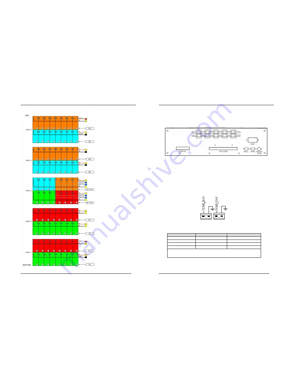
TOP VIEW INTENAL SHELF BATTERY POSITION


I


FIG.2.5.B 

-

20

NS3000 Series User Manual    rev.01 

2.6 Control and Communication Cabling 

fig.  2-6  shown,  the  Relay  card  dry  contact  interface  (J2-J10),  communication  interface  (RS232  interface,  485 

interface and SNMP card interface) and parallel card position. 


Fig 2-6 Dry contact interface and communication interface 

The UPS accepts external signal from zero-voltage (dry) contacts connected through external dry contact terminals 

produced  and  phoenix  terminals.  Through  software  programming,  these  signals  become  active  when  these  contacts 

connect  to  +24V  to  ground.The  cables  connected  to  DRY  terminal  must  be  separated  from  power  cables.  Moreover, 

these  cables  should  be  double  insulated  with  a  typical  0.5  to  1.5  mm

2


cross-section  area  for  a  maximum  connection 

length between 25 and 50 meters. 

2.6.1 Dry Contact Interface of Battery and Environmental Temperature Detection (Optional) 

The input dry contact J2 and J3 can detect the temperature of batteries and environment respectively, which can be 

used in environment monitoring and battery temperature compensation 1. 

J2 and J3 interfaces diagram are shown in fig 2-7, the description of interface is in table 2-2. 

J2

J3


Fig 2-7 Diagram of J2 and J3 dry contact for temperature detecting 

  Table 2-2   

Position 

Name 

Purpose 

J2.1 

TEMP_BAT 

Battery temperature detection 

J2.2 

GND 

Power ground 

J3.1 

TEMP_ENV 

Environment temperature detection 

J3.2 

GND 

Power ground 

Note:   

Specified  temperature  sensor  is  required  for  temperature  detection  (R25=5kOhm,  B25/50=3275), 

please confirm with the manufacturer, or contact local maintenance engineers when placing an order. 

Содержание NS3000 10 kVA

Страница 1: ...1 NS3000 Series User Manual Rev 01 UPS NS3000 10 20 30kVA USER Manual 2 NS3000 Series User Manual Rev 01...

Страница 2: ...te the static switch if excessive voltage is present at the bypass input when the bypass source is deenergized If this function is not installed and enabled there must be a warning label on the extern...

Страница 3: ...al rev 01 3 2 3 Auto Restart Mode 29 3 2 4 Bypass Mode 29 3 2 5 Maintenance Mode 29 3 2 6 ECO Mode 29 3 2 7 Frequency Converters Mode 29 3 2 8 Parallel connection redundancy mode 30 3 3 Battery Manage...

Страница 4: ...s any mistake for accessories contact with shipper or provider 1 3 Environment Checking Before installing UPS please check these items as below 1 Is the UPS operation environment temperature above 25...

Страница 5: ...sary a system of extractor fans should be installed to aid cooling air flow An air filter should be used when the UPS is to operate in a dirty environment and should be regularly cleaned to maintain a...

Страница 6: ...l Against ambient corrosive gases l Against excessive humidity and heat sources l Against dust l With the current fire prevention requirements l The operating environment temperature is within 20 25...

Страница 7: ...supply the installed device should l Sensitive to DC Class B or class A in the network l Insensitive to transient current pulses l Have an average sensitivity that is adjustable between 0 3A 1A 14 NS3...

Страница 8: ...epartment After the equipment has been finally positioned and secured connect the power cables as described in the following procedures 1 Verify that all the external input distribution switches of th...

Страница 9: ...2 5 A Pay attention all cable are marked and have different color 6 Connect the battery according fig 2 5 A don t connect A and B cable in the shelf 1 7 In shelf 1 on the left connect the cable mark...

Страница 10: ...d be double insulated with a typical 0 5 to 1 5 mm 2 cross section area for a maximum connection length between 25 and 50 meters 2 6 1 Dry Contact Interface of Battery and Environmental Temperature De...

Страница 11: ...Note 1 The emergency stop action within the UPS will shut down the rectifier inverter and static bypass However it does not internally disconnect the mains input and batterypower supply To disconnect...

Страница 12: ...neral warning dry contact interface diagram Table 2 7 Position Name Purpose J9 1 ALARM_NC Integrated warning relay normally closed will be open during warning J9 2 ALARM_NO Integrated warning relay no...

Страница 13: ...25 NS3000 Series User Manual rev 01 2 7 Installation Diagram 26 NS3000 Series User Manual rev 01 a 10KVA 30KVA terminal block NS3030 NS3010 NS3020...

Страница 14: ...ss module can be removed for maintenance Fig 3 1 System principle framework 28 NS3000 Series User Manual rev 01 3 1 2 Bypass During normal system operation the load is connected to the inverter but in...

Страница 15: ...e output frequency The range of output frequency is 40Hz 70Hz Under this mode static bypass is unavailable but battery can be selected according to the actual requirements of battery mode Frequency Co...

Страница 16: ...4 1 Typical 1 N parallel operation system Note when the load exceeds the capacity of the single device we recommended an external manual Bypass The cables for the parallel operation provide double in...

Страница 17: ...Warning Please confirm that UPS output rotating switch point to UPS with anti misoperation stop plate for rotating switch is fixed well 1 Close UPS bypass input switch and input switch in turns The LC...

Страница 18: ...aution Before making this operation read messages on display to be sure that bypass supply is regular and the inverter is synchronous with it so as not to risk a short interruption in powering the loa...

Страница 19: ...chapter introduces the functions and operation instructions of the parts on UPS operator control and display panel in detail and provides LCD display information including LCD display types detailed...

Страница 20: ...tus indicator Steady red Failure 6 1 2 Audible Alarm buzzer There are two different types of audible alarm during UPS operation as shown in table 6 3 Table 6 3 Description of audible alarm Alarm Purpo...

Страница 21: ...rface you can select each function and press ENTER press ENTER again it will display Confirm interface 6 2 5 State Display The alarm page as below press left and right arrow to select STA in homepage...

Страница 22: ...inverted power supply status Bypass power supply The system is in bypass power supply status No power supply System no output Battery equalized charging Battery is in boost charging Battery float char...

Страница 23: ...hows the power is normally supply by the bypass 8 Open maintenance bypass switch and close mains input switch the inverter automatically starts and UPS operates in the normal mode after 60 seconds 9 C...

Страница 24: ...harge V cell 2 4V cell selectable from 2 3V cell 2 45V cell Constant current and constant voltage charge mode Battery Charging Power Max Current kW 10 UPS capacity selectable from 0 20 UPS capacity NS...

Страница 25: ...eutral cable A 1 7 In Frequency2 Hz 50 60 Switch time between bypass and inverter ms Synchronized switch 1ms Bypass voltage tolerance Vac Upper limit 10 15 or 20 default 20 Lower limit 10 20 30 or 40...

Отзывы: