-
15
-
NS3000 Series User Manual rev.01
2.4.3 Battery
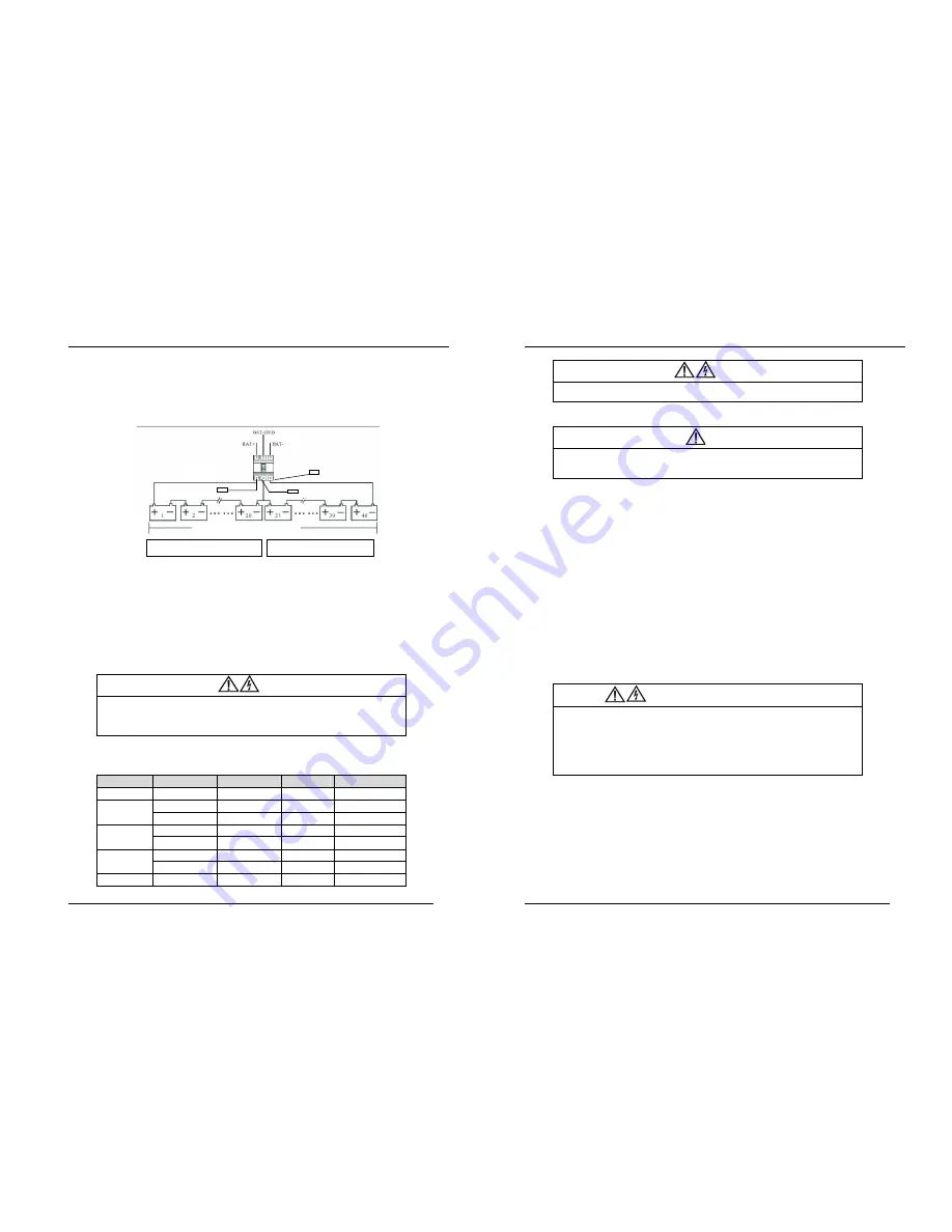
A battery string is composed of 40 batteries connected in series, maximum is possible install 2 strings 40batteries (B1-B2
in this document). The positive, the negative and middle point (the joint part between the 20th and 21st battery) cable
must push through a DC circuit breaker before connecting to corresponding UPS . For detailed wiring please refers to fig
2-4 below:
Fig 2-4 Diagram of batteries connected in series
2.4.3 UPS Output
A main output switch has been installed in UPS; the user shall install the overcurrent protective device on the bypass
and on each output of the external distribution cabinet.
2.5 Power Cables
Design the cables according to the descriptions in this section and local regulatory wiring standards, and the
environmental conditions should be taken into consideration. Refer to IEC60950-1 table 3B.
Warning
Prior cabling the UPS, confirm the status and positions of the switches of the UPS rectifier input
power supply / bypass power supply and mains power distribution board.
Ensure that these switches are opened and attached with WARNING label so as to prevent
unauthorized operation to these switches.
2.5.1 Maximum stable state current and configuration of minimum cable system
Table 2-1
Model Name
NS3010
NS3020
NS3030
UPS Power
10KVA
20KVA
30KVA
Rated current A
15A
30A
45A
Main Input
Cable mm2
4
6
10
Rated current A
15A
30A
45A
Output
Cable mm2
4
6
10
Rated current A
18A
36A
53A
Battery
Cable mm2
6
10
16
PE
Cable mm2
4
10
10
Forty batteries in series connection in total
Batt +
Batt-
Batt - N
Batt +
Batt -
B1 + series
B1 - series
-
16
-
NS3000 Series User Manual rev.01
Warning
FAILURE TO FOLLOW ADEQUATE EARTHING PROCEDURES CAN RESULT IN EMI, ELECTRIC
SHOCK HAZARD OR RISK OF FIRE, SHOULD AN EARTH FAULT OCCUR.
2.5.2 Cable Connection
Important
The operations described in this section must be performed by authorized electricians or qualified
technical personnel.. If you have any difficulties, do not hesitate to contact our Customer Service &
Support department .
After the equipment has been finally positioned and secured, connect the power cables as described in the following
procedures:
1.
Verify that all the external input distribution switches of the UPS are completely opened (off position) and the UPS
internal maintenance bypass switch is opened. Attach necessary warning signs to these switches to prevent
unauthorized operation.
2.
Open the door of the cabinet, remove the left bottom cover and then the input and output terminal, battery terminal
and earth terminal are visible.
3.
Connect the input earth wire to input earth terminal. Please note: the earth wire shall be connected in accordance
with related local or state regulation
4.
If in UPS, same electric supply input is used for the by-pass and main input AC input cables should be connected
with the input terminal of UPS (Main input L1ma – L2mb – L3mc
and the output load cables are connected
with the output terminal of UPS
(Output L1oa - L2oA - L3oC). If in UPS, two electric supply inputs are used for
the rectifier and by-pass, the AC input cables should be respectively connected with the main input terminal of UPS
(Main input L1ma - L2mb – L3mc
and the input terminal of the bypass,L1ba,L2bb,L3bc and the short circuit
copper bars between the main circuit and the bypass have to be removed; fastening moment of force is
30kg(M5), 50kg(M6), 180kg(M8). Attention is given to phase sequence and the short circuit at a joint between cable
terminals. If the phase sequence is wrong UPS show an alarm
5.
Connect the battery cables between the UPS battery terminals and battery switch.
ENSURE CORRECT Polarity.
Warning-Hazardous battery terminal voltage
≥
400Vdc
The operations described in this section must be performed by authorized electricians or qualified
technical personnel.
Ensure the correct polarity connection between the battery terminals and the UPS terminals: Positive
terminal to positive terminal, negative terminal to negative terminal, The middle poin of the batteies is
Neutral point in the UPS.
Disconnect in the tray 1 and tray 5 the cable marked A and B. Do not connect the cables and close
the battery circuit breakers before getting the approval from the commissioning engineer.
6.
Re-install all the protective covers.


