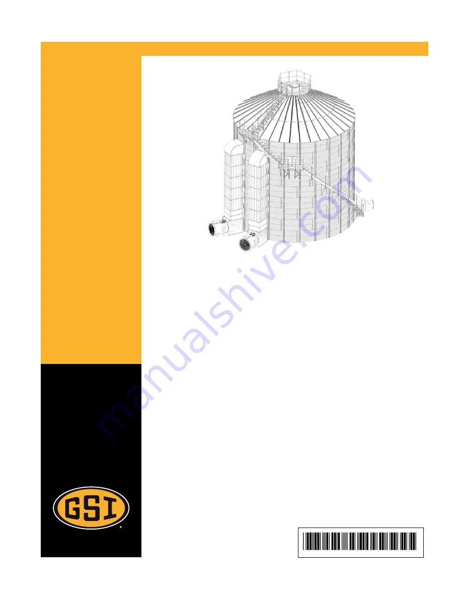
TopDry — Platforms and BinStairs
Models:
24 FT – 36 FT
Installation Manual
PNEG-2077
Version 1.1
Date: 09-27-16
Страница 1: ...TopDry Platforms and Bin Stairs Models 24 FT 36 FT Installation Manual PNEG 2077 Version 1 1 Date 09 27 16 PNEG 2077 ...
Страница 2: ...ions photos and specifications in this manual are based on the latest information available at the time of publication The right is reserved to make changes at any time without notice 2 PNEG 2077 TopDry Platforms and Bin Stairs ...
Страница 3: ...cket 36 Assembling the Bottom Sidewall Attachment Bracket 38 Chapter 4 Installing Winding Bin Stairs Intermediate to Eave 39 Installing the Sidewall Attachment brackets Intermediate Platform to Eave Platform 40 Installing the Stair Sections Intermediate Platform to Eave Platform 41 Installing the Winding Bin Stair Handrails 43 Chapter 5 Eave Platform 45 Assembling the Eave Platform 46 Installing t...
Страница 4: ...NOTES 4 PNEG 2077 TopDry Platforms and Bin Stairs ...
Страница 5: ... inform others as required Unqualified persons must stay out of the work area at all times Alterations must not be made to the equipment Alterations can produce dangerous situations resulting in SERIOUS INJURY or DEATH This equipment must be installed in accordance with the current installation codes and applicable regula tions which must be carefully followed in all cases Authorities having juris...
Страница 6: ...bol indicates an imminently hazardous situation which if not avoided will result in serious injury or death This symbol indicates a potentially hazardous situation which if not avoided can result in serious injury or death This symbol indicates a potentially hazardous situation which if not avoided can result in minor or moderate injury This symbol is used to address practices not related to perso...
Страница 7: ...tructions Carefully read all safety messages in this manual and safety signs on your machine Keep signs in good condition Replace missing or damaged safety signs Be sure new equipment components and repair parts include the current safety signs Replacement safety signs are available from the manufacturer Learn how to operate the machine and how to use controls properly Do not let anyone operate wi...
Страница 8: ...re Roof damage can result from excessive vacuum or internal pressure from fans or other air moving systems The manu facturer does not warrant this type of roof damage Adequate ventilation or makeup air devices must be pro vided for all powered air handling systems The manufacturer does not recommend the use of down ward flow systems suction Severe roof damage can result from any blockage of air pa...
Страница 9: ...ving jurisdiction must be consulted before installations are made When necessary you must consider the installation location relative to electrical fuel and water utilities Personnel operating or working around equipment must read this manual This manual must be delivered with equipment to its owner Failure to read this manual and its safety instructions is a misuse of the equipment This product i...
Страница 10: ...n Left and right middle inside and outside DC 2180 Non text fan Warnings Left middle out side and right middle inside DC 1540 Danger High Voltage Warning Stay Clear of Rotat ing Blade Warning Flying Objects Hazard Left middle out side and right middle inside DC 995 Warning Shear Point To replace a damaged or missing decal contact us to receive a free replacement GSI Decals 1004 E Illinois St Assum...
Страница 11: ...f sheet that can be used to verify that all personnel have read and understood the safety instructions This sign off sheet is provided for your convenience and personal record keeping Date Employee Name Supervisor Name ST 0007 PNEG 2077 TopDry Platforms and Bin Stairs 11 ...
Страница 12: ...NOTES 12 PNEG 2077 TopDry Platforms and Bin Stairs ...
Страница 13: ...ed in this Chapter Assembling the Intermediate Platform Sections Installing the Wall Attachment Brackets Installing the Intermediate Platform Installing the Handrails for Intermediate Platform PNEG 2077 TopDry Platforms and Bin Stairs 13 ...
Страница 14: ... pan 7 together with sixteen truss head bolts 1 and sixteen flange nuts 3 IMPORTANT Arrange Intermediate support angles 5 as shown A NOTE Tighten the truss head bolts 1 before the platform floor is installed to the bin Figure 2 1 Assembling the platform floor first platform section 1 5 16 x 3 4 in truss head bolt S 10267 6 Outside support angle WBS 0015 3 5 16 in flange nut S 3611 7 Platform floor...
Страница 15: ...d flange nuts 3 NOTE Tighten the flange bolts 2 before the platform is installed to the bin Figure 2 2 Assembling the inside kick plate first platform section 2 5 16 x 3 4 in flange bolt S 6606 7 Platform floor pan WBS 0011 3 5 16 in flange nut S 3611 23 Inside kick plate WBS 0014 6 Outside support angle WBS 0015 PNEG 2077 TopDry Platforms and Bin Stairs 15 ...
Страница 16: ...f the intermediate support angle 5 Make sure the four bolt pattern in sidewall attachment gusset 10 is at the bottom and facing the bin wall Hand tighten the flange bolts 2 before the platform is leveled on the bin Figure 2 3 Assembling the sidewall attachment gussets first platform section 2 5 16 x 3 4 in flange bolt S 6606 5 Intermediate support angle WBS 0017 3 5 16 in flange nut S 3611 10 Side...
Страница 17: ...mediate support angles 5 as shown A NOTE Tighten the truss head bolts 1 before the platform floor is installed to the bin Figure 2 4 Assembling the platform floor second platform section 1 5 16 x 3 4 in truss head bolt S 10267 6 Outside support angle WBS 0015 3 5 16 in flange nut S 3611 7 Platform floor pan WBS 0011 5 Intermediate support angle WBS 0017 A Arrangement of intermediate support angles...
Страница 18: ... flange nuts 3 NOTE Tighten the flange bolts 2 before the platform is installed to the bin Figure 2 5 Assembling the inside kick plate second platform section 2 5 16 x 3 4 in flange bolt S 6606 7 Platform floor pan WBS 0011 3 5 16 in flange nut S 3611 23 Inside kick plate WBS 0014 6 Outside support angle WBS 0015 18 PNEG 2077 TopDry Platforms and Bin Stairs ...
Страница 19: ...the truss head bolts 1 before the platform floor is installed to the bin Figure 2 6 Assembling the stringer support bracket second platform section 1 5 16 x 3 4 in truss head bolt S 10267 7 Platform floor pan WBS 0011 3 5 16 in flange nut S 3611 11 Stringer support bracket WBS 0027 5 Intermediate support angle WBS 0017 PNEG 2077 TopDry Platforms and Bin Stairs 19 ...
Страница 20: ...f the intermediate support angle 5 Make sure the four bolt pattern in sidewall attachment gusset 10 is at the bottom and facing the bin wall Hand tighten the flange bolts 2 before the platform is leveled on the bin Figure 2 7 Assembling the sidewall attachment gussets second platform section 2 5 16 x 3 4 in flange bolt S 6606 5 Intermediate support angle WBS 0017 3 5 16 in flange nut S 3611 10 Sid...
Страница 21: ...cket 14 lines up on a hill 3 Install standard bin bolts B and flange nuts C to secure the wall attachment brackets 14 to the sidewall NOTE The bolts must be installed with the bolt head on the inside of the bin Install each wall attachment bracket 14 with the angle open outward and a hole to hole gap F of 18 75 in Install the outer two wall attachment brackets 14 to the stiffeners in the sidewall ...
Страница 22: ...le next to the square in the wall attachment bracket 14 to position the platform assembly below the access door Install the sidewall attachment gusset 10 on the outside of the angle in the wall attach ment brackets 14 Tighten the flange bolts 2 between the sidewall attachment gussets 10 and wall attachment brackets 14 before tightening the bolts connecting the sidewall attach ment gussets 10 and t...
Страница 23: ...e bolts 2 with the bolt head towards the inside of the platform Hand tighten the flange bolts 2 Figure 2 10 Installing the handrail posts for first platform 2 5 16 x 3 4 in flange bolt S 6606 7 Platform floor pan WBS 0011 3 5 16 in flange nut S 3611 9 Platform handrail post WBS 0019 6 Outside support angle WBS 0015 23 Inside kick plate WBS 0014 PNEG 2077 TopDry Platforms and Bin Stairs 23 ...
Страница 24: ...ange bolts 2 and flange nuts 3 NOTE Leave the flange bolts 2 hand tight until the platform stiffening straps 16 are attached in the next step Figure 2 11 Installing the outside handrail kick braces for first platform 2 5 16 x 3 4 in flange bolt S 6606 14 Wall attachment bracket WBS 0010 3 5 16 in flange nut S 3611 15 Outside handrail kick brace WBS 0020 9 Platform handrail post WBS 0019 24 PNEG 20...
Страница 25: ...k braces 15 using flange bolts 2 and flange nuts 3 Figure 2 12 Installing the platform stiffening straps for first platform 2 5 16 x 3 4 in flange bolt S 6606 15 Outside handrail kick brace WBS 0020 3 5 16 in flange nut S 3611 16 Platform stiffening strap WBS 0083 PNEG 2077 TopDry Platforms and Bin Stairs 25 ...
Страница 26: ...nstall the sidewall attachment gusset 10 on the outside of the angle in the wall attach ment bracket 14 Tighten the flange bolts 2 between the sidewall attachment gussets 10 and wall attachment brackets 14 before tightening the bolts connecting the sidewall attach ment gussets 10 and the intermediate support angles 14 underneath the platform to aid in leveling the second platform section Figure 2 ...
Страница 27: ...teen flange nuts 3 to secure the two platform sections Figure 2 14 Installing the double platform splice 1 5 16 x 3 4 in truss head bolt S 10267 7 Platform floor pan WBS 0011 2 5 16 x 3 4 in flange bolt S 6606 20 Double platform splice For 24 ft and 30 ft bins WBS 0084 For 36 ft bins WBS 0045 3 5 16 in flange nut S 3611 23 Inside kick plate WBS 0014 5 Intermediate support angle WBS 0017 PNEG 2077 ...
Страница 28: ... nuts 3 NOTE Install the flange bolts 2 with the bolt head towards the inside of the platform Hand tighten the flange bolts 2 Figure 2 15 Installing the handrail posts for second platform 2 5 16 x 3 4 in flange bolt S 6606 7 Platform floor pan WBS 0011 3 5 16 in flange nut S 3611 9 Platform handrail post WBS 0019 6 Outside support angle WBS 0015 28 PNEG 2077 TopDry Platforms and Bin Stairs ...
Страница 29: ...flange bolts 2 and flange nuts 3 NOTE Leave the flange bolts 2 loose until the platform stiffening straps 16 are attached in the next step Figure 2 16 Installing the outside handrail kick braces for second platform 2 5 16 x 3 4 in flange bolt S 6606 14 Wall attachment bracket WBS 0010 3 5 16 in flange nut S 3611 15 Outside handrail kick brace WBS 0020 9 Platform handrail post WBS 0019 PNEG 2077 To...
Страница 30: ...stalling the platform stiffening strips for second platform 2 5 16 x 3 4 in flange bolt S 6606 15 Outside handrail kick brace WBS 0020 3 5 16 in flange nut S 3611 16 Platform stiffening strap WBS 0083 10 Tighten and level the handrail posts 9 11 Tighten the outside handrail kick braces 15 and the platform stiffening straps 16 30 PNEG 2077 TopDry Platforms and Bin Stairs ...
Страница 31: ...achment plate 12 to the inside of the outside support angle 6 using flange bolts 2 and flange nuts 3 Figure 2 18 Installing the stringer attachment plates for second section 2 5 16 x 3 4 in flange bolt S 6606 11 Stringer support bracket WBS 0027 3 5 16 in flange nut S 3611 12 Stringer attachment plate WBS 0026 6 Outside support angle WBS 0015 PNEG 2077 TopDry Platforms and Bin Stairs 31 ...
Страница 32: ... self drill ing screws 4 per bracket in the platform sections NOTE Install the self drilling screw 4 from the outside of the handrail bracket 17 3 Align the intermediate platform lower handrail 82 with the hole located in the middle of the handrail posts 9 and secure using self drilling screws 4 in the platform sections NOTE Install the self drilling screw 4 from the outside of the handrail post 9...
Страница 33: ...n this Chapter Assembling the 4 Step Winding Bin Stair Section Assembling the 5 Step Winding Bin Stair Section Assembling the Standard Sidewall Attachment Bracket Assembling the Bottom Sidewall Attachment Bracket PNEG 2077 TopDry Platforms and Bin Stairs 33 ...
Страница 34: ... the outside of the stringer sections and flange nuts 3 on the inside Leave the flange bolts 2 loose in the slots to allow the stairs to wrap correctly around the bin Figure 3 1 Assembling the 4 step stair section 2 5 16 x 3 4 in flange bolt S 6606 65 4 step inside stringer 3 5 16 in flange nut S 3611 66 4 step outside stringer 34 Step WBS 0007 AH Stringer identification mark Bin Diameter ft Insid...
Страница 35: ... the outside of the stringer sections and flange nuts 3 on the inside Leave the flange bolts 2 loose in the slots to allow the stairs to wrap correctly around the bin Figure 3 2 Assembling the 5 step stair section 2 5 16 x 3 4 in flange bolt S 6606 43 5 step inside stringer 3 5 16 in flange nut S 3611 44 5 step outside stringer 34 Step WBS 0007 AH Stringer identification mark Bin Diameter ft Insid...
Страница 36: ...e top of sidewall sheet bracket 45 and secure them using flange bolts 2 and flange nuts 3 2 Attach a channel kick brace 47 to the support channel 46 and sidewall sheet bracket 45 with flange bolts 2 and flange nuts 3 Figure 3 3 Assembling the Standard Sidewall Attachment Bracket 2 5 16 x 3 4 in flange bolt S 6606 46 Support channel WBS 0002 3 5 16 in flange nut S 3611 47 Channel kick brace WBS 000...
Страница 37: ...3 NOTE If an inside handrail is needed replace inside stringer support 48 with another bin stair handrail post 49 Figure 3 4 Assembling the Standard sidewall attachment bracket 2 5 16 x 3 4 in flange bolt S 6606 48 Inside stringer support WBS 0088 3 5 16 in flange nut S 3611 49 Bin stair handrail post WBS 0004 46 Support channel WBS 0002 PNEG 2077 TopDry Platforms and Bin Stairs 37 ...
Страница 38: ...uts 3 2 Attach the inside stringer support 48 and bin stair handrail post 49 to the support channel 46 using flange bolts 2 and flange nuts 3 NOTE If an inside handrail is needed replace inside stringer support 48 with another bin stair handrail post 49 Figure 3 5 Assembling the bottom sidewall attachment bracket 2 5 16 x 3 4 in flange bolt S 6606 46 Support channel WBS 0002 3 5 16 in flange nut S...
Страница 39: ...overed in this Chapter Installing the Sidewall Attachment brackets Intermediate Platform to Eave Platform Installing the Stair Sections Intermediate Platform to Eave Platform Installing the Winding Bin Stair Handrails PNEG 2077 TopDry Platforms and Bin Stairs 39 ...
Страница 40: ... U to the hole in the horizontal seam next to the intermediate platform assembly The bolts must be installed with the bolt head on the inside of the bin 2 Repeat the above step to continue installing another sidewall attachment bracket assembly U one ring above around the sidewall towards the eave NOTE Install the sidewall attachment bracket assembly U with a hole to hole gap V of 46 875 in Figure...
Страница 41: ...andrail post 49 and the inside stringer support 48 and secure using flange bolts 2 and flange nuts 3 NOTE Hand tighten the flange bolts 2 Figure 4 2 Installing the first 5 step stair section 2 5 16 x 3 4 in flange bolt S 6606 49 Bin stair handrail post WBS 0004 3 5 16 in flange nut S 3611 AA First 5 step stair section 48 Inside stinger support WBS 0088 PNEG 2077 TopDry Platforms and Bin Stairs 41 ...
Страница 42: ... stair section AB will be aligned to the eave platform whenever it is installed NOTE Hand tighten the flange bolts 2 Figure 4 3 Installing the next 5 step stair section 2 5 16 x 3 4 in flange bolt S 6606 49 Bin stair handrail post WBS 0004 3 5 16 in flange nut S 3611 AA First 5 step stair section 48 Inside stinger support WBS 0088 AB Second 5 step stair section IMPORTANT As the stair sections are ...
Страница 43: ...ged end up and secure it to the handrail brackets 17 using two self drilling screws 4 per bracket NOTE The swage at the top end will need to be cut off before it is attached to the handrail post in the platform Install the self drilling screws 4 from the outside of the handrail brackets 17 3 Starting at the top of the winding bin stair assembly and working towards the bottom orient and align the l...
Страница 44: ...rs for Eave platform 2 5 16 x 3 4 in flange bolt S 6606 49 Handrail post WBS 0004 3 5 16 in flange nut S 3611 41 Upper handrail WBS 0048 XXX 1 4 1 4 x 1 in self drilling screw 42 Lower handrail WBS 0049 XXX 1 17 Handrail brackets WBS 0319 44 PNEG 2077 TopDry Platforms and Bin Stairs 1 XXX Denotes the bin diameter ...
Страница 45: ...5 Eave Platform Topics Covered in this Chapter Assembling the Eave Platform Installing the Eave Platform Installing the Eave Platform Handrails PNEG 2077 TopDry Platforms and Bin Stairs 45 ...
Страница 46: ...h sixteen truss head bolts 1 and sixteen flange nuts 3 IMPORTANT Arrange the intermediate support angles 5 as shown A NOTE Tighten the truss head bolts 1 before the platform floor is installed to the bin Figure 5 1 Assembling the platform floor first platform section 1 5 16 x 3 4 in truss head bolt S 10267 6 Outside support angle WBS 0015 3 5 16 in flange nut S 3611 7 Platform floor pan WBS 0011 5...
Страница 47: ...truss head bolts 1 before the platform floor is installed to the bin Figure 5 2 Assembling the stringer support bracket first platform section 1 5 16 x 3 4 in truss head bolt S 10267 7 Platform floor pan WBS 0011 3 5 16 in flange nut S 3611 11 Stringer support bracket WBS 0027 5 Intermediate support angle WBS 0017 PNEG 2077 TopDry Platforms and Bin Stairs 47 ...
Страница 48: ...intermediate support angle 5 Hand tighten the flange bolts 2 before the platform is leveled on the bin Figure 5 3 Assembling the sidewall attachment gussets first platform section 2 5 16 x 3 4 in flange bolt S 6606 5 Intermediate support angle WBS 0017 3 5 16 in flange nut S 3611 10 Sidewall attachment gusset WBS 0018 NOTE Make sure the four bolt pattern in sidewall attachment gusset 10 is at the ...
Страница 49: ...tachment brackets 14 to aid in leveling the platform assembly Figure 5 4 Assembling the wall attachment brackets to the sidewall attachment gussets first platform section 2 5 16 x 3 4 in flange bolt S 6606 10 Sidewall attachment gusset WBS 0018 3 5 16 in flange nut S 3611 14 Wall attachment bracket WBS 0010 5 Assemble a stringer attachment plate 12 to the outside of the stringer support bracket 11...
Страница 50: ...r attachment plates first platform section 2 5 16 x 3 4 in flange bolt S 6606 11 Stringer support bracket WBS 0027 3 5 16 in flange nut S 3611 12 Stringer attachment plate WBS 0026 6 Outside support angle WBS 0015 50 PNEG 2077 TopDry Platforms and Bin Stairs ...
Страница 51: ...ate support angles 5 as shown A NOTE Tighten the truss head bolts 1 before the platform floor is installed to the bin Figure 5 6 Assembling the platform floor second platform section 1 5 16 x 3 4 in truss head bolt S 10267 6 Outside support angle WBS 0015 3 5 16 in flange nut S 3611 7 Platform floor pan WBS 0011 5 Intermediate support angle WBS 0017 A Arrangement of intermediate support angles Vie...
Страница 52: ... Tighten the flange bolts 2 before the platform is installed to the bin Figure 5 7 Assembling the platform end toe board and inside kick plate second platform section 2 5 16 x 3 4 in flange bolt S 6606 7 Platform floor pan WBS 0011 3 5 16 in flange nut S 3611 8 Platform end toe board WBS 0022 6 Outside support angle WBS 0015 23 Inside kick plate WBS 0014 52 PNEG 2077 TopDry Platforms and Bin Stair...
Страница 53: ...ntermediate support angle 5 Hand tighten the flange bolts 2 before the platform is leveled on the bin Figure 5 8 Assembling the sidewall attachment gussets second platform section 2 5 16 x 3 4 in flange bolt S 6606 5 Intermediate support angle WBS 0017 3 5 16 in flange nut S 3611 10 Sidewall attachment gusset WBS 0018 NOTE Make sure the four bolt pattern in sidewall attachment gusset 10 is at the ...
Страница 54: ...tion the platform assembly above the eave Hand tighten the flange bolts 2 between the sidewall attachment gussets 10 and wall attachment brackets 14 to aid in leveling the platform assembly Figure 5 9 Assembling the wall attachment brackets to the sidewall attachment gussets second platform section 2 5 16 x 3 4 in flange bolt S 6606 10 Sidewall attachment gusset WBS 0018 3 5 16 in flange nut S 361...
Страница 55: ...E The bolts must be installed with the bolt head on the inside of the bin Tighten the flange bolts 2 between the sidewall attachment gussets 10 and wall attachment brackets 14 before tightening the bolts connecting the sidewall attach ment gussets 10 and the intermediate support angles 14 underneath the platform to aid in leveling the platform assembly Align the first and last hole of the wall att...
Страница 56: ...ange bolts 2 with the bolt head towards the inside of the platform Hand tighten the flange bolts 2 Figure 5 11 Installing the handrail posts for first platform section 2 5 16 x 3 4 in flange bolt S 6606 6 Outside support angle WBS 0015 3 5 16 in flange nut S 3611 7 Platform floor pan WBS 0011 5 Intermediate support angle WBS 0017 9 Platform handrail post WBS 0019 56 PNEG 2077 TopDry Platforms and ...
Страница 57: ...lts 2 and flange nuts 3 NOTE Leave the flange bolts 2 loose until the platform stiffening straps 16 are attached in the next step Figure 5 12 Installing the outside handrail kick braces for first platform section 2 5 16 x 3 4 in flange bolt S 6606 14 Wall attachment bracket WBS 0010 3 5 16 in flange nut S 3611 15 Outside handrail kick brace WBS 0020 9 Platform handrail post WBS 0019 PNEG 2077 TopD...
Страница 58: ...with flange bolts 2 and flange nuts 3 as shown Figure 5 13 Installing the platform stiffening strips for first platform section 2 5 16 x 3 4 in flange bolt S 6606 15 Outside handrail kick brace WBS 0020 3 5 16 in flange nut S 3611 16 Platform stiffening strap WBS 0083 58 PNEG 2077 TopDry Platforms and Bin Stairs ...
Страница 59: ...diate support angles 14 underneath the platform to aid in leveling the platform assembly Align the first and last hole of the wall attachment bracket 14 with the top D and bottom E holes in the horizontal seam of the first ring Align and install the wall attachment bracket of the second platform with the angle open outward and a hole to hole gap F of 18 75 in with the adjacent wall attachment brac...
Страница 60: ...s 3 to secure the two platform sections Figure 5 15 Installing the double platform splice for second section 1 5 16 x 3 4 in truss head bolt S 10267 7 Platform floor pan WBS 0011 2 5 16 x 3 4 in flange bolt S 6606 20 Double platform splice For 24 ft and 30 ft bins WBS 0084 For 36 ft ft bins WBS 0045 3 5 16 in flange nut S 3611 23 Inside kick plate WBS 0014 5 Intermediate support angle WBS 0017 60 ...
Страница 61: ...nge bolts 2 with the bolt head towards the inside of the platform Hand tighten the flange bolts 2 Figure 5 16 Installing the handrail posts for second platform section 2 5 16 x 3 4 in flange bolt S 6606 7 Platform floor pan WBS 0011 3 5 16 in flange nut S 3611 8 Platform end toe board WBS 0022 6 Outside support angle WBS 0015 9 Platform handrail post WBS 0019 PNEG 2077 TopDry Platforms and Bin Sta...
Страница 62: ... using flange bolts 2 and flange nuts 3 NOTE Hand tighten the handrail kick braces 13 Figure 5 17 Installing the handrail kick braces for second platform 2 5 16 x 3 4 in flange bolt S 6606 9 Platform handrail post WBS 0019 3 5 16 in flange nut S 3611 13 Handrail kick brace WBS 0025 5 Intermediate support angle WBS 0017 62 PNEG 2077 TopDry Platforms and Bin Stairs ...
Страница 63: ...bolts 2 and flange nuts 3 NOTE Leave the flange bolts 2 hand tight until the platform stiffening straps 16 are attached in the next step Figure 5 18 Installing the outside handrail kick braces for second platform 2 5 16 x 3 4 in flange bolt S 6606 14 Wall attachment bracket WBS 0010 3 5 16 in flange nut S 3611 15 Outside handrail kick brace WBS 0020 9 Platform handrail post WBS 0019 PNEG 2077 TopD...
Страница 64: ...lling the platform stiffening straps for second platform 2 5 16 x 3 4 in flange bolt S 6606 15 Outside handrail kick brace WBS 0020 3 5 16 in flange nut S 3611 16 Platform stiffening strap WBS 0083 12 Tighten and level the handrail posts 9 13 Tighten the outside handrail kick braces 15 and the platform stiffening straps 16 64 PNEG 2077 TopDry Platforms and Bin Stairs ...
Страница 65: ...uble platform upper handrail 21 into the single platform upper handrail 18 of the first platform section before securing with the self drilling screws 4 NOTE Install the self drilling screw 4 from the outside of the handrail bracket 17 4 Align the single platform lower handrail 19 with the hole located in the middle of the handrail posts 9 and secure using self drilling screws 4 NOTE Install the s...
Страница 66: ... upper handrail WBS 0023 3 5 16 in flange nut S 3611 19 Single platform lower handrail WBS 0024 4 1 4 x 1 in self drilling screw S 7229 21 Double platform upper handrail WBS 0039 9 Platform handrail post WBS 0019 22 Double platform lower handrail WBS 0038 17 Handrail bracket WBS 0319 66 PNEG 2077 TopDry Platforms and Bin Stairs ...
Страница 67: ...pics Covered in this Chapter Installing the Sidewall Attachment Brackets Intermediate Platform to Bin Bottom Installing the Stair Sections Intermediate Platform to Bin Bottom Installing the Winding Bin Stair Handrails PNEG 2077 TopDry Platforms and Bin Stairs 67 ...
Страница 68: ...f 37 5 in between the sidewall attachment bracket assembly U and the right most wall attachment bracket in the platform assembly G The bolts must be installed with the bolt head on the inside of the bin 2 Repeat the above step to continue installing the sidewall attachment brackets U one ring below around the sidewall for the remaining rings NOTE Install each sidewall attachment bracket assembly U...
Страница 69: ...all attachment bracket assembly Y with a hole to hole gap V of 46 875 in The bolts must be installed with the bolt head on the inside of the bin Figure 6 2 Installing the sidewall attachment bracket to the bottom ring B Standard bin bolt with sealing washer U Sidewall attachment bracket assembly C Flange nut V 46 875 in D Top hole in horizontal seam X Second hole from top E Bottom hole in horizont...
Страница 70: ...the inside stringer support 48 and secure using flange bolts 2 and flange nuts 3 NOTE Hand tighten the flange bolts 2 Figure 6 3 Installing the 4 step stair section 2 5 16 x 3 4 in flange bolt S 6606 49 Bin stair handrail post WBS 0004 3 5 16 in flange nut S 3611 G Platform assembly 12 Stringer attachment plate WBS 0026 AC 4 step stair section 48 Inside stinger support WBS 0088 3 Align the top end...
Страница 71: ...make sure that any offset AF between the stringers is consis tent throughout the winding bin stair assembly 5 Align the top end of the last 5 step stair section AE to the bottom of the previous 5 step stair sec tion AD and secure using flange bolts 2 and flange nuts 3 NOTE Hand tighten the flange bolts 2 6 Align the bottom end of the 5 step stair section AE to the handrail post 49 and the inside s...
Страница 72: ...16 x 3 4 in flange bolt S 6606 49 Bin stair handrail post WBS 0004 3 5 16 in flange nut S 3611 AD Previous 5 step stair section 48 Inside stinger support WBS 0088 AE Last 5 step stair section 7 Tighten all the flange bolts 2 after all stair sections are installed to the bin wall 72 PNEG 2077 TopDry Platforms and Bin Stairs ...
Страница 73: ...er the installed handrail and secure it to the handrail brackets 17 using two self drilling screws 4 per bracket with swaged end up NOTE The swaged end should be pushed into the handrail as far as it can go Install the self drilling screws 4 from the outside of the handrail brackets 17 4 Starting at the top of the winding bin stair assembly and working towards the bottom orient and align the first...
Страница 74: ...s for Intermediate platform 2 5 16 x 3 4 in flange bolt S 6606 49 Handrail post WBS 0004 3 5 16 in flange nut S 3611 41 Upper handrail WBS 0048 XXX 2 4 1 4 x 1 in self drilling screw 42 Lower handrail WBS 0049 XXX 2 17 Handrail brackets WBS 0319 74 PNEG 2077 TopDry Platforms and Bin Stairs 2 XXX Denotes the bin diameter ...
Страница 75: ...sixtieth 60th month from the date of purchase extended warranty period During the extended warranty period GSI will replace the frame or basket components that prove to be defective under normal conditions of use without charge excluding the labor transportation and or shipping costs incurred in the performance of this extended warranty Conditions and Limitations THERE ARE NO WARRANTIES THAT EXTEN...
Страница 76: ...ould be carefully followed in all cases Authorities having jurisdiction should be consulted before installations are made 1004 E Illinois St Assumption IL 62510 0020 Phone 1 217 226 4421 Fax 1 217 226 4420 www gsiag com GSI is a worldwide brand of AGCO Corporation Copyright 2016 by GSI Group Printed in the USA CN 326466 ...