background image

109 ENGLISH 


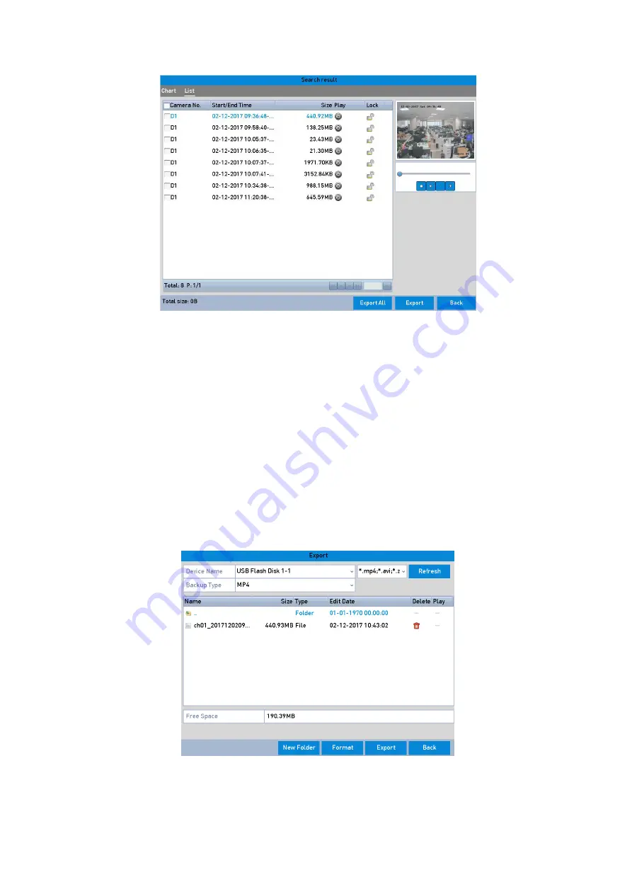
Result of Normal Video Search for Backup 

5.


Export the video files or picture files.  

Click the <Export All> button to export all of the files. 
Or you can select recording files you want to back up and click the <Export> button to enter the 

<Export> interface. 

Note: 

If the inserted USB device is not recognized: 
Click the <Refresh> button. 
Reconnect the device. 
Check for compatibility from the vendor. 

You can also format USB flash drives or USB HDDs via the device. 


Export by Normal Video Search using USB Flash Drive 

Содержание GD-RN-AC2004P

Страница 1: ...grundig security com User Manual GD RN AC2004P GD RN AP8632P GD RN AC2416N GD RN AT8864N GD RN AC2416P GD RN CT8832N GD RN AP8616P GD RT AT819128N...

Страница 2: ...nected to the PoE Interfaces 49 2 3 5 Configuring the PoE Interface 51 3 Live View 53 3 1 Introduction of Live View 53 3 2 Operations in the Live View mode 53 3 3 Adjusting the Live View Settings 60 3...

Страница 3: ...laying Back by System Logs 101 6 1 8 Playing Back External File 102 6 1 9 Playing Back Pictures 102 6 2 Auxiliary Functions of Playback 103 6 2 1 Playing Back Frame by Frame 103 6 2 2 Thumbnails View...

Страница 4: ...the POS Alarm 133 10 VCA Alarm 135 10 1 Face Detection 135 10 2 Vehicle Detection 136 10 3 Line Crossing Detection 137 10 4 Intrusion Detection 138 10 5 Region Entrance Detection 140 10 6 Region Exiti...

Страница 5: ...g the Network Delay and Packet Loss 165 12 4 2 Exporting the Network Packet 166 12 4 3 Checking the Network Status 167 12 4 4 Checking the Network Statistics 167 13 RAID 169 13 1 Configuring an Array...

Страница 6: ...rting Log Files 188 16 3 Importing Exporting the IP Camera Info 191 16 4 Importing Exporting Configuration Files 191 16 5 Upgrading the System 192 16 5 1 Upgrading by Local Backup Device 192 16 5 2 Up...

Страница 7: ...l Further information about the product like Data Sheets CE Documents etc can also be found on the CD in the product package This User Guide is a user manual for IP Recorders NVRs Please see in the ta...

Страница 8: ...tion and VGA video output at up to a 2K resolution Multiple screen display in Live View is supported and the display sequence of channels is adjustable Live View screen can be switched in a group Manu...

Страница 9: ...RN AP8616P GD RN AP8632P and GD RN AT8864N only 8 recording time periods with separated recording types POS Information Overlay on an image by GD RN AP8616P GD RN AP8632P GD RN AT8864N and GD RN CT883...

Страница 10: ...ection Vehicle Plate Behavior Analysis People Counting and Heat Map Connectable to a thermal network camera for GD RN AP8616P GD RN AP8632P GD RN AT8864N and GD RN CT8832N Supports the advanced search...

Страница 11: ...bles the IP Camera to save the recording files in the local storage when the network is disconnected and it synchronizes the files to the NVR when the network is resumed Remote Reverse Playback via RT...

Страница 12: ...NGLISH Source code of the application software for demo Development support and training for the application system 1 3 Front Panel View GD RN AT8864N GD RN CT8832N GD RN AT8864N CT8832N Panel Descrip...

Страница 13: ...tatus can be changed by pressing and holding on the ESC button for more than 3 seconds in the Live View mode 2 IR Receiver Receiver for IR Remote control 3 Front Panel Lock Locks or unlocks the panel...

Страница 14: ...he cursor Checks the checkbox in the checkbox fields Adjusts the iris of the camera in the PTZ Control mode Generates video clips for backup in the Playback mode Enters exits the folder of a USB devic...

Страница 15: ...ns to select the next and previous video files Cycles through channels in the Live View mode Controls the movement of the PTZ Camera in the PTZ Control mode ENTER Confirms selection in any of the Menu...

Страница 16: ...icators POWER Turns blue when NVR is powered up HDD Blinks red when HDD is reading writing Tx Rx Blinks blue when network connection is functioning normally Alarm Turns red when alarm comes up 2 USB I...

Страница 17: ...tected Blinking red HDD is reading writing Tx Rx Blinking blue indicates that the network communication is normal 4 Power switch Powers the device on off Solid blue indicates that the device is powere...

Страница 18: ...ol the NVR using default Device ID 255 without any additional steps Device ID 255 is the default universal device identification number shared by the NVRs You may also pair an IR Remote to a specific...

Страница 19: ...ollows Press the DEV key on the IR Remote Any existing Device ID will be erased from the unit s memory and it will no longer function with the NVR Note Re enabling the IR Remote requires pairing to an...

Страница 20: ...User is not logged on 1 Hold the Power On Off button 1 down for five seconds to display the User Name Password prompt 2 Press the Enter button 12 to display the on screen keyboard 3 Input the User Na...

Страница 21: ...u Call a PTZ Preset by using the numeric buttons in the PTZ Control settings Turn audio on off in the Playback mode 7 PLAY Go to the Playback mode Auto scan in the PTZ Control menu 8 INFO Zoom in the...

Страница 22: ...re is no response after you press any button on the remote control follow the procedure below to troubleshoot Steps 1 Go to Menu Settings General More Settings by operating the front control panel or...

Страница 23: ...e recommended device list from your provider The operation of the mouse Description of the Mouse Control Name Action Description Left Click Single Click Live View Select the channel and show the Quick...

Страница 24: ...Keyboard 1 OSD Keyboard 2 Description of the buttons on the OSD Keyboard Icon Description Icon Description Number English letter Lowercase Uppercase Backspace Switch the keyboard Space Positioning th...

Страница 25: ...6 USB 3 0 interface Universal Serial Bus USB ports for additional devices such as a USB mouse and a USB Hard Disk Drive HDD 7 RS 232 Interface Connector for RS 232 devices 8 eSATA Connects external SA...

Страница 26: ...HDMIInterface HDMI video output connector 5 ALARM IN Connector for Alarm Input ALARM OUT Connector for alarm output 6 LAN Network Interface 1 10 100 1000 Mbps self adaptive Ethernet interface 7 USB In...

Страница 27: ...ce DB9 connector for VGA output Display local video output and menu 5 HDMIInterface HDMI video output connector 6 LAN Network Interface 1 10 100 1000 Mbps self adaptive Ethernet interface for GD RN AC...

Страница 28: ...ouse and a USB Hard Disk Drive HDD 6 RS 232 Interface Connector for RS 232 devices 7 VGA DB9 connector for VGA output Display local video output and menu 8 RS 485 Interface Half duplex connector for R...

Страница 29: ...sal Serial Bus USB 3 0 ports for additional devices such as a USB mouse and a USB Hard Disk Drive HDD 4 LAN 4 10 100 1000 Mbps self adaptive Ethernet interfaces 5 eSATA Connects external SATA HDD CD D...

Страница 30: ...B Connector for the keyboard 11 GND Ground needs to be connected when the NVR starts up 12 Power supply modules Only one power supply module is provided by default Two power supply modules are optiona...

Страница 31: ...on the front panel should be red indicating that the device gets the power supply 2 Press the POWER button on the front panel The Power indicator LED should turn blue indicating that the unit begins...

Страница 32: ...Password No operation is allowed before activation You can also activate the device via a Web Browser Grundig Viewer or the SCMS Client Software Steps 1 Enter the same password in the text field of C...

Страница 33: ...Password interface Please refer to the Chapter Resetting Your Password for the instructions of password resetting Export GUID File Note Please keep your GUID file properly for future password resetti...

Страница 34: ...the screen Release the mouse when the pattern is done Draw the Pattern Note Connect at least four dots to draw the pattern Each dot can be connected once only 3 Draw the same pattern again to confirm...

Страница 35: ...he Admin User has the permission to unlock the device Please configure the pattern first before unlocking Please refer to Configuring the Unlock Pattern 1 Right click the mouse on the screen and selec...

Страница 36: ...Normal Login Dialog Box Login and Logout User Login If the NVR has logged out you must log in the device before operating the menu and other functions 3 Select the User Name in the dropdown list Logi...

Страница 37: ...password of the Admin User you can reset the password by importing the GUID file The GUID file must be exported and saved in the local U flash disk after you have activated the device refer to Chapter...

Страница 38: ...ser Management interface to edit the Admin User and to export the GUID file 2 2 Using the Wizard for Basic Configuration By default the Setup Wizard starts once the NVR has loaded as shown below Start...

Страница 39: ...k Fault tolerance Also one self adaptive 10M 100M 1000M network interface is provided for GD RN AC2416N GD RN AC2416P GD RN AP8616P and GD RN AP8632P 4 Click the Next button after you configured the b...

Страница 40: ...u to the RAID configuration window Note The RAID is supported by GD RN AT8864N and GD RN AT819128N only Array Management 7 Click the Next button to enter the Array Management window 8 Click the Next b...

Страница 41: ...nactive status then you can click the inactive icon of the camera to set the password to activate it You can also select multiple cameras from the list and click the One touch Activate to activate the...

Страница 42: ...amera to enter the IP Camera Management interface For the IP camera detected online in the same network segment the Password status shows whether it is active or inactive IP Camera Management interfac...

Страница 43: ...Click OK to finish the acitavting of the IP camera Then the security status of camera will be changed to Active 2 3 2 Adding the Online IP Cameras The main function of the NVR is to connect the netwo...

Страница 44: ...amera Management interface Adding IP Camera Interface 2 The online cameras with the same network segment will be detected and displayed in the camera list 3 Select the IP camera from the list and clic...

Страница 45: ...er to the following table for the description of the icons Description of Icons Icon Explanation Icon Explanation Edit basic parameters of the camera Add the detected IP camera The camera is disconnec...

Страница 46: ...automatically switch to the H 265 stream of the IP camera which supports an H 265 video format for the initial access 2 3 3 Editing the Connected IP Cameras and Configuring Customized Protocols After...

Страница 47: ...twork information and the Password of the camera Password Configuration of the Camera 3 Click OK to save the settings and to exit the interface Configuring the customized protocols To connect the netw...

Страница 48: ...h Example rtsp 192 168 1 55 554 ch1 main av_stream Protocol Name Edit the name for the Custom Protocol Enable Sub stream If the network camera does not support Sub stream or if the Sub stream is not n...

Страница 49: ...as Up to 4 network cameras can be connected to 4 Port models 8 network cameras to 8 Port models and 16 network cameras to 16 Port models If you disable the PoE interface you can also connect to the on...

Страница 50: ...mera can t be edited The IP Address of the camera can only be edited in the Network Configuration interface see Chapter 11 1 12 1 Configuring General Settings for detailed information Edit IP Camera I...

Страница 51: ...nter the PoE Configuration interface 2 Menu Camera Camera PoE Configuration 3 Click the radio button of each PoE channel to switch and You can click the radio button of the PoE Channel to enable or di...

Страница 52: ...different IP Camera models When the transmission distance reaches 100 to 250 meters it must use the CAT5E or CAT6 network cable to connect with the PoE interface When the transmission distance reache...

Страница 53: ...al Record Schedule Record Motion Detection VCA and Alarm Triggered Record Alarm and Record Event Exception Motion Detection VCA Sensor Alarm or Exception information appears at the lower left corner o...

Страница 54: ...2P When both the HDMI and VGA are connected the HDMI is used as main output and the VGA is used as the aux output For GD RN AT819128N the following applies To configure HDMI 1 and VGA Simultaneous Out...

Страница 55: ...the screen for channel 2 Show multi screen Press the PREV FOCUS button Manually switch screens Next screen Right Down direction button Previous screen Left Up direction button Auto switch Press the E...

Страница 56: ...and manage the cameras Playback Enter the Playback interface and start playing back the video of the selected channel immediately PTZ Enter the PTZ Control interface Output Mode Four modes of output...

Страница 57: ...e main output monitor the menu operation is not available while Aux output mode is enabled Quick Setting Toolbar in the Live View mode On the screen of each channel there is a Quick Setting Toolbar wh...

Страница 58: ...n on the live image You can zoom in the image to different proportions 1 to16X by moving the sliding bar from to You can also scroll the mouse wheel to control the zoom in out The Image Settings icon...

Страница 59: ...ye Four different display modes are available You can select a display mode as demand 180 Panorama Switch the Live View image to the 180 Panorama view 360 Panorama Switch the Live View image to the 36...

Страница 60: ...2N HDMI 1 HDMI 2 and VGA outputs are provided for GD RN AT819128N HDMI 2 video output at up to 4K resolution HDMI and VGA outputs are provided for GD RN AC2004P GD RN AC2416N GD RN AC2416P GD RN AP861...

Страница 61: ...Live View 4 Click the Apply button to save the settings You can also click and drag the camera to the desired window on the Live View interface to set the camera order 3 Set the Stream Type for the Li...

Страница 62: ...annel zero encoding is supported as an option for you Steps 1 Enter the Live View Settings interface Menu Configuration Live View 2 Select the Channel Zero Encoding tab Live View Channel Zero Encoding...

Страница 63: ...ore you control the PTZ Camera Steps 1 Enter the PTZ Settings interface Menu Camera PTZ PTZ Settings 2 Click the PTZ Parameters button to set the PTZ parameters PTZ General 3 Choose the camera for the...

Страница 64: ...Preset as well 3 Enter the Preset No 1 255 in the Preset text field and click the Set button to link the location to the Preset Repeat steps 2 to3 to save more presets You can click the Clear button t...

Страница 65: ...trols can be set to move the PTZ to different key points and have it stay there for a set duration before moving on to the next key point The key points are corresponding to the presets The presets ca...

Страница 66: ...can delete all the key points by clicking the Clear button for the selected Patrol or click the Clear All button to delete all of the key points for all of the patrols Calling Patrols Calling a Patrol...

Страница 67: ...Z Camera and then click the Stop button to stop it The movement of the PTZ is recorded as the pattern Calling Patterns Follow the procedure to move the PTZ Camera according to the predefined patterns...

Страница 68: ...ps 1 Enter the PTZ Control interface Menu Camera PTZ PTZ Settings 2 Use the directional button to wheel the camera to the location where you want to set the limit and click the Left Limit or Right Lim...

Страница 69: ...an and click the Linear Scan button again to stop it You can click the Restore button to clear the defined Left Limit and Right Limit data and the dome needs to reboot to make settings take effect One...

Страница 70: ...is 5s 4 Click the button again to inactivate it 4 3 PTZ Control Panel To enter the PTZ Control panel there are two ways supported OPTION 1 In the PTZ Settings interface click the PTZ button on the lo...

Страница 71: ...Direction button and the auto cycle button Zoom Focus Iris Zoom Focus Iris The speed of the PTZ movement Light on off Wiper on off 3D Zoom Image Centralization Menu Switch to the PTZ Control interfac...

Страница 72: ...DD General HDD General 2 Check the storage mode of the HDD Click Advanced to check the Storage mode of the HDD If the HDD mode is Quota please set the Maximum Record Capacity and the Maximum Picture C...

Страница 73: ...265 or H 264 Enable H 264 Mode check the checkbox to enable Once enabled the Max Bitrate Mode Max Bitrate Kbps and Max Bitrate Range Recommend are not configurable Enabling it helps to ensure the high...

Страница 74: ...e Chapter 5 8 Configuring Redundant Recording and Capture Record Audio Check the checkbox to enable or disable audio recording Video Stream Main Stream and Sub stream are selectable for recording When...

Страница 75: ...chedule Set the Record Schedule and the camera will automatically start stop recording according to the configured schedule Note In this chapter we take the record schedule procedure as an example the...

Страница 76: ...Motion Detection and an Alarm POS This is a Recording triggered by POS and an Alarm Supported by GD RN AP8616P GD RN AP8632P and GD RN AT8864N only Note You can delete the set schedule by clicking th...

Страница 77: ...h other 4 Select the record type in the dropdown list Note To enable Motion Alarm M A motion or alarm M A motion and alarm and VCA Video Content Analysis triggered recording and capture you must confi...

Страница 78: ...ngs Draw the schedule I Click on the color icons you can choose the schedule type as Continuous or Event Draw the Schedule II Click the Apply button to validate the settings 7 Optional If the settings...

Страница 79: ...record which is triggered by the detected motion Steps 1 Enter the Motion Detection interface Menu Camera Motion Motion Detection 2 Configure Motion Detection 1 Choose the camera you want to configure...

Страница 80: ...ure Schedule 5 4 Configuring Alarm Triggered Recording and Capture Follow the procedure to configure alarm triggered recording or capture Steps 1 Enter the Alarm Settings interface Menu Configuration...

Страница 81: ...vel menu Repeat the above steps to configure other Alarm Input parameters If the settings can also be applied to other Alarm Inputs click Copy and choose the Alarm Input No Copy Alarm Input 3 Edit the...

Страница 82: ...Detection Object Removal Detection Audio Loss Exception Detection Sudden Change of Sound Intensity Detection and Defocus Detection Steps 1 Enter the VCA Settings interface and select a Camera for the...

Страница 83: ...lly cancel the record and capture The manual recording and manual continuous capture is prior to the scheduled recording and capture Steps 1 Enter the Manual settings interface Menu Manual Or press th...

Страница 84: ...the capture schedule After rebooting all the continuous capture will be canceled 5 7 Configuring Holiday Recording and Capture Follow the steps to configure the record or capture schedule on holiday f...

Страница 85: ...g redundant recording and capture which means saving the record files and captured pictures not only in the R W HDD but also in the redundant HDD will effectively enhance the data safety and reliabili...

Страница 86: ...to the upper level menu Repeat the above steps for configuring other channels 5 9 Configuring the HDD Group for Recording and Capture You can group the HDDs and save the record files and captured pict...

Страница 87: ...umber in the dropdown list of Record under HDD Group 3 Check the channels you want to save in this group 4 Click Apply to save the settings Note After having configured the HDD groups you can configur...

Страница 88: ...files related to the Playback channels 4 You can click the button to pop up the File Management interface Click the Locked File tab to check and export the locked files Locked File Management In the...

Страница 89: ...to show the results Export Search Result 5 Protect the record files 1 Find the record files you want to protect and then click to change it to indicating that the file is locked Note The record files...

Страница 90: ...roperty to Read only 4 Click OK to save the settings and to go back to the upper level menu Note You cannot save any files in a read only HDD If you want to save files in the HDD change the property t...

Страница 91: ...Quick Setting Toolbar Note In the instant Playback mode only record files recorded during the last five minutes on this channel will be played back 6 1 2 Playing Back by Normal Search Playback by Chan...

Страница 92: ...The Main Stream or Sub stream for recording is configurable in Menu Record Parameters 5 Select a date in the calendar and click on the left toolbar to play the video file Playback Calendar If there ar...

Страница 93: ...93 ENGLISH Playback interface Toolbar of Playback You can click the channel s to execute Simultaneous Playback of multiple channels...

Страница 94: ...the Intrusion Detection Filter video files by setting the Target Characters Operations Audio on Mute Start Stop clipping Capture Picture Lock File Add default tag Add customized tag File management fo...

Страница 95: ...rough the less effective information When you select the Smart Playback mode the system will analyze the video containing the motion line or intrusion detection information mark it with green color an...

Страница 96: ...fy the start point and end point of the line Intrusion Detection Click and specify 4 points to set a quadrilateral region for Intrusion Detection Only one region can be set Motion Detection Click and...

Страница 97: ...rch Interface 5 Select the Minor Type of VCA from the drop down list Please refer to Chapter 9 VCA Alarm for the details of VCA Detection types Note For configuring the VCA recording please refer to C...

Страница 98: ...event Please refer to the Table under 6 1 2 for the description of buttons on the toolbar 6 1 5 Playing Back by Tag Video tag allows you to record related information like people and location of a ce...

Страница 99: ...ut Tag Name Note Max 64 tags can be added to a single video file 3 Tag management Click to enter the File Management interface and click Tag to manage the tags You can check edit and delete tag s Tag...

Страница 100: ...ub periods simultaneously on the screens Steps 1 Enter the Playback interface Menu Playback 2 Select Sub periods from the drop down list in the upper left corner of the page to enter the Sub periods P...

Страница 101: ...og Information 3 Click the Log Search tab to enter the Playback by System Logs 4 Set the search time and click the Search button System Log Search Interface 5 Choose a log with a record file and click...

Страница 102: ...t 3 Select and click to play it back And you can adjust the Playback Speed by clicking and 6 1 9 Playing Back Pictures The captured pictures stored in the HDDs of the device can be searched and viewed...

Страница 103: ...ck Frame by Frame Play video files frame by frame in case of checking image details of the video when abnormal events happen Using a Mouse Go to the Playback interface If you choose Playback of the re...

Страница 104: ...e preview thumbnails of the video files Select and double click on a required thumbnail to enter the full screen playback Thumbnails View Note The thumbnail view is supported only in the 1X Single cam...

Страница 105: ...5 File Management You can manage the video clips captured pictures in Playback locked files and tags you have added in the Playback mode Steps 1 Enter the Playback interface 2 Click on the toolbar to...

Страница 106: ...n Note The time duration of record files on a specified channel cannot exceed one day Otherwise the message box Max 24 hours are allowed for quick export will pop up Quick Export Interface 2 Select th...

Страница 107: ...l all record files are exported Export Finished 4 Check the backup result Choose the record file in the Export interface and click to check it Note The Player player exe will be exported automatically...

Страница 108: ...erface Menu Export Normal Picture 2 Select the cameras to search 3 Set the Search Condition and click the Search button to enter the Search Result interface The matched video files or pictures are dis...

Страница 109: ...can select recording files you want to back up and click the Export button to enter the Export interface Note If the inserted USB device is not recognized Click the Refresh button Reconnect the device...

Страница 110: ...lash drives USB HDDs USB writers SATA writers or eSATA HDDs Quick Backup and Normal Backup are supported Steps 1 Enter the Export interface Menu Export Event 2 Select the cameras to search 3 Select th...

Страница 111: ...ed Playback Pictures You may also select video clips or captured pictures in the Playback mode to export directly during Playback using USB devices USB flash drives USB HDDs USB writers SATA writers o...

Страница 112: ...ice Management 2 Backup device management Click the New Folder button if you want to create a new folder in the backup device Select a record file or folder in the backup device and click if you want...

Страница 113: ...ion will be disabled when the device works in the Hot Spare mode It s highly recommended to restore the defaults of the device after switching the working mode of the Hot Spare device to normal mode t...

Страница 114: ...us list When the working device works properly the working status of the Hot Spare device is displayed as No record When the working device gets offline the Hot Spare device will record the video of t...

Страница 115: ...ion Setup Interface 2 Set up the Detection Area and the Sensitivity Check Enable Motion Detection use the mouse to draw detection area s and drag the Sensitivity bar to set the Sensitivity Click and s...

Страница 116: ...n be set within each day 3 Click Apply to save the settings Note Time periods shall not be repeated or overlapped Set Arming Schedule of Motion Detection 5 Click the Handling tab to set up Alarm Respo...

Страница 117: ...the Settings button to set up its Alarm Response Actions Alarm Input Setup Interface 3 Optional Enable One key Disarming for Alarm Input 1 Local 1 1 Check the checkbox of Enable One Key Disarming 2 Cl...

Страница 118: ...ve the settings Note Time periods shall not be repeated or overlapped Repeat the above steps to set up an Arming Schedule of other days of a week You can also use the Copy button to copy an Arming Sch...

Страница 119: ...he checkbox of Alarm Inputs to copy the settings to them Copy Settings of Alarm Input 8 3 Detecting a Video Loss Alarm Detect video loss of a channel and take alarm response action s Steps 1 Enter the...

Страница 120: ...te Time periods shall not be repeated or overlapped Set Arming Schedule of Video Loss 5 Select the Linkage Action tab to set up an Alarm Response Action of Video Loss please refer to Chapter 8 6 Setti...

Страница 121: ...to detect Video Tampering 3 Click to set up a Handling Action for Video Tampering 3 Set the Arming Schedule and Alarm Response Actions of the channel 1 Click the Arming Schedule tab to set the Arming...

Страница 122: ...th the working device Steps Enter the Exception interface of System Configuration and handle various exceptions Menu Configuration Exceptions Please refer to Chapter 8 6 Setting Alarm Response Actions...

Страница 123: ...creen images will be switched at an interval of 10 seconds default Dwell Time A different Dwell Time can be set by going to Menu Configuration Live View Full Screen Monitoring Dwell Time Auto switch w...

Страница 124: ...larm Output Trigger an Alarm Output when an alarm is triggered Steps 1 Enter the Alarm Output interface Menu Configuration Alarm Alarm Output 2 Select an Alarm Output and set an Alarm Name and a Dwell...

Страница 125: ...or Clearing an Alarm Output Manually A Sensor Alarm can be triggered or cleared manually If Manually Clear is selected in the dropdown list for the Dwell Time of an Alarm Output the Alarm can be clea...

Страница 126: ...126 ENGLISH Clear or Trigger Alarm Output Manually...

Страница 127: ...ach device is the half of its channel amount 3 Check the checkbox to Enable the POS feature POS Settings 4 Select the POS Protocol to Universal Protocol EPSON AVE or NUCLEUS Note When the new protocol...

Страница 128: ...o save the settings AVE Settings NUCLEUS 1 Click Set to configure the NUCLEUS settings 2 Enter the Employee No Shift No and the Terminal No in the field The matching message sent from the POS device w...

Страница 129: ...ote IP Address of the device sending the POS Message UDP Connection Settings USB RS 232 Connection Configure the Port parameters of the USB to RS 232 convertor including the Serial Port Number the Bau...

Страница 130: ...oding format from the drop down list 2 Select the Overlay mode of the characters to display in Scrolling or Page mode 3 Select the Font Size to Small Medium or Large 4 Set the Overlay Time of the char...

Страница 131: ...to other POS s Copy POS Settings 9 2 Configuring the Overlay Channel You can assign the POS machine to corresponding channel on which you want to overlay Steps 1 Enter the POS Settings interface Menu...

Страница 132: ...set the POS Privacy Information to not display on the image Steps 1 Enter the POS Settings interface Menu Configuration POS POS Settings 2 Click this button of the Privacy Settings to enter the POS Pr...

Страница 133: ...4 Click the Trigger Channel tab and select one or more channels to record or become Full Screen Monitoring when a POS Alarm is triggered 5 Set the Arming Schedule of the channel Select the Arming Sch...

Страница 134: ...elect the PTZ Linking tab and set the PTZ Linkage of the POS Alarm Set PTZ Linking parameters and click the OK button to complete the settings of the Alarm Input Note Please check whether the PTZ or s...

Страница 135: ...detailed instructions for all of the VCA Detection types 10 1 Face Detection The Face Detection function detects the face that appears in the surveillance scene and certain actions can be taken when...

Страница 136: ...the surveillance center and you can upload the captured picture to a FTP server Steps 1 Enter the VCA Settings interface Menu Camera VCA 2 Select the camera to configure the VCA 3 You can click the ch...

Страница 137: ...e to Line Crossing Detection 5 Check the Enable checkbox to enable this function 6 Click to configure the Trigger Channel arming schedule and Linkage Actions for the Line Crossing Detection alarm 7 Cl...

Страница 138: ...w it Note Up to 4 rules can be configured Draw Line for Line Crossing Detection Click Apply to activate the settings 10 4 Intrusion Detection The Intrusion Detection function detects people vehicles o...

Страница 139: ...nd drag the slider to set the detection Sensitivity 3 Sensitivity Range 1 100 The value of the sensitivity defines the size of the object which can trigger the alarm The higher the value is the more e...

Страница 140: ...A You can click the checkbox of Save VCA Picture to save the captured pictures of VCA Detection 3 Select the VCA Detection Type to Region Entrance Detection 4 Check the Enable checkbox to enable this...

Страница 141: ...a purse dangerous materials etc and a series of actions can be taken when the Alarm is triggered Note Please refer to the Chapter 9 4 Intrusion Detection for operating steps to configure the Unattend...

Страница 142: ...uch as the sudden increase decrease of the sound intensity and certain actions can be taken when the alarm is triggered Steps 1 Enter the VCA Settings interface Menu Camera VCA 2 Select the camera to...

Страница 143: ...for operating steps to configure the Scene Change Detection The Sensitivity in the Rule Settings ranges from 1 to 100 and the higher the value is the more easily the change of scene can trigger the al...

Страница 144: ...0 then the Alarm is triggered immediately when the object is entering the region Up to 4 rules can be configured 10 14 People Gathering Detection Note This function is only available for the NVR mode...

Страница 145: ...AT819128N The Parking Detection function detects illegal parking in places such as highways one way streets etc and a series of actions can be taken when the Alarm is triggered Note Please refer to Ch...

Страница 146: ...tart searching The search results of Face Detection pictures are displayed in a List or in a Chart 5 Play the Face Picture related video file You can double click on a Face Picture to play its related...

Страница 147: ...d click Export All to enter the Export interface Click Export to export all pictures to the storage device 11 3 Plate Search This function is not available in all models You can search and view the ma...

Страница 148: ...A Search Heat Map 2 Select the Camera for the heat map processing 3 Select the Report Type to Daily Report Weekly Report Monthly Report or Annual Report 4 Set the Statistics Time 5 Click the Counting...

Страница 149: ...ct the Camera s for the Advanced Search 3 Specify the Start Time and the End Time for searching the Thermal Imaging Detection results 4 Select the type to Fire Detection Ship Detection Temperature Det...

Страница 150: ...on Network 2 Select the General tab Network Settings Interface 3 In the General Settings interface you can configure the following settings Working Mode NIC Type IPv4 Address IPv4 Gateway MTU DNS DHCP...

Страница 151: ...address Mode The parameters of the two NIC cards can be configured independently You can select LAN1 or LAN2 in the NIC Type field for parameter settings You can select one NIC card as Default Route...

Страница 152: ...red in the DynDNS website DynDNS Settings Interface PeanutHull Enter the User Name and the Password obtained from the PeanutHull website NO IP Enter the account information in the corresponding fields...

Страница 153: ...in 12 2 2 Configuring the NTP Server A Network Time Protocol NTP Server can be configured on your NVR to ensure the accuracy of the system date time Steps 1 Enter the Network Settings interface Menu...

Страница 154: ...r at the National Time Center IP Address 210 72 145 44 If the NVR is set up in a more customized network NTP software can be used to establish a NTP Server used for Time Synchronization 12 2 3 Configu...

Страница 155: ...e the same as the Alarm Monitoring Port configured in the software default Port is 7200 Multicast IP The multicast can be configured to realize Live View for more than the maximum number of cameras th...

Страница 156: ...ress is 192 0 0 64 you may access the device by entering https 192 0 0 64 443 via the web browser Note The HTTPS Port can be only configured through the web browser 1 Open the web browser and enter th...

Страница 157: ...Create Self signed Certificate 2 Enter the Country Host Name IP Validity and other information 3 Click OK to save the settings OPTION 2 Create the authorized certificate 1 Click the Create button to...

Страница 158: ...ication to all designated users if an Alarm Event or a Motion Event etc is detected or if the Administrator Password is changed Before configuring the Email Settings the NVR must be connected to a Loc...

Страница 159: ...ication Feature User Name The User Name of the sender s account registered on the SMTP Server Password The Password of the sender s account registered on the SMTP Server SMTP Server The SMTP Server IP...

Страница 160: ...segment Network UPnP and Manual Mapping UPnPTM Universal Plug and Play UPnP can permit the device to seamlessly discover the presence of other network devices on the network and establish functional n...

Страница 161: ...sh button to get the latest status of the Port Mapping UPnP Settings Finished Auto OPTION 2 Manual If you select Manual as the Mapping Type you can edit the External Port on your demand by clicking to...

Страница 162: ...the Port No for each device should be unique External Port Settings Dialog Box 3 Click the Apply button to save the settings 4 You can click the Refresh button to get the latest status of the Port Map...

Страница 163: ...r the Virtual Server Settings page of the router fill in the blank of the Internal Source Port with the Internal Port Value and the blank of External Source Port with the External Port Value and other...

Страница 164: ...heckbox Enable Virtual Host 3 Click the Save button to save the setting 4 Enter the IP Camera Management interface of the NVR The Connect column appears on the far right side of the camera list Config...

Страница 165: ...n on the interface The Traffic data is refreshed every 1 second 12 4 Configuring Network Detection You can obtain the Network Connecting Status of the NVR through the Network Detection function includ...

Страница 166: ...the Network Traffic interface Menu Maintenance Net Detect 2 Click the Network Detection tab to enter the Network Detection interface 3 Select the backup device from the dropdown list called Device Nam...

Страница 167: ...following message box pops out Network Status Checking Result If the message box pops out with other information instead of this one you can click the Network button to show the Quick Setting interfa...

Страница 168: ...the Bandwidth of the IP Camera the Bandwidth of Remote Live View the Bandwidth of Remote Playback the Bandwidth of the Net Receive Idle and the Bandwidth of Net Send Idle 4 You can click Refresh to ge...

Страница 169: ...can enable the RAID function on your demand Note The GD RN AT8864N GD RN CT8832N and GD RN AT819128N support the RAID 0 RAID 1 RAID 5 RAID 6 and RAID 10 array types Before you start Please install the...

Страница 170: ...ls As the default Array Type is RAID 5 please install at least 3 HDDs on your device If more than 10 HDDs are installed 2 arrays can be configured Steps 1 Enter the RAID Configuration interface Menu H...

Страница 171: ...n the range of 4 to 16 4 Click the OK button to create the Array Note If the number of HDDs you select is not compatible with the requirement of the RAID Level the error message box will pop up 5 You...

Страница 172: ...graded status Steps 1 Enter the Array Settings interface The disk 3 is lost Menu HDD RAID Array 2 Click the Array tab to back to the Array Settings interface and click to configure the Array Rebuild N...

Страница 173: ...ed on the Firmware interface Steps 1 Enter the Firmware interface to check the information of the firmware including the Version the Maximum Physical Disk Quantity the Maximum Array Quantity the Auto...

Страница 174: ...n the NVR starts up if there exits any Uninitialized HDD Message Box of Uninitialized HDD Click the Yes button to initialize it immediately or you can perform the following steps to initialize the HDD...

Страница 175: ...o Normal HDD Status Changes to Normal Note Initializing the HDD will erase all data on it 14 2 Managing the Network HDD You can add the allocated NAS or disk of IP SAN to the NVR and use it as a Netwo...

Страница 176: ...e available NAS disks 3 Select the NAS disk from the list shown below 4 Or you can just manually enter the directory in the text field of NetHDD Directory 5 Click the OK button to add the configured N...

Страница 177: ...gs interface Menu Record Advanced 2 Select the eSATA Type to Export or Record Capture from the dropdown list of eSATA Export use the eSATA for backup Refer to Backup using eSATA HDDs in Chapter 7 1 2...

Страница 178: ...Property The HDD property can be set to Redundancy Read only or Read Write R W Before setting the HDD property please set the storage mode to Group refer to step1 4 of Chapter 14 4 1 Setting HDD Grou...

Страница 179: ...NVR must be rebooted to enable the changes to take effect Storage Mode Settings Interface 4 Select a Camera for which you want to configure the Quota 5 Enter the Storage Capacity in the text fields of...

Страница 180: ...all the data on the HDD to an inserted eSATA disk manually Refer to Chapter 12 8 HDD Detection for details of S M A R T detection Before you start An eSATA disk should be connected to the device Step...

Страница 181: ...h is displayed on the list as shown below View HDD Status 1 Note If the status of HDD is Normal or Sleeping that means that it works normally If the status is Uninitialized or Abnormal please initiali...

Страница 182: ...nique The S M A R T Self Monitoring Analysis and Reporting Technology is a monitoring system for the HDD to detect and report on various indicators of reliability in the hopes of anticipating failures...

Страница 183: ...M A R T HDD Self evaluation Note If you want to use the HDD even when the S M A R T checking is failed you can check the checkbox Continue to use the disk when self evaluation is failed Bad Sector De...

Страница 184: ...onfiguration Exceptions 2 Select the Exception Type to HDD Error from the dropdown list 3 Click the checkbox s below to select the HDD Error Alarm Type s as shown below Note The Alarm Type can be sele...

Страница 185: ...Date Format Time Format and Display Mode OSD Configuration Interface 6 You can use the mouse to click and drag the text frame on the preview window to adjust the OSD position 7 Click the Apply button...

Страница 186: ...ote Up to 4 Privacy Mask zones can be configured and the size of each area can be adjusted 5 The configured Privacy Mask zones on the window can be cleared by clicking the corresponding Clear Zone1 4...

Страница 187: ...or click on the Up Down arrow to set the value of the Brightness Contrast or Saturation 4 Select the Enable Rotate function to Clockwise 270 degrees or OFF When OFF is selected the image is restored...

Страница 188: ...rm Network and HDD tabs to view the system information of the device Device Information Interface Note You can add the device to your Grundig SCMS via scanning the QR Code 16 2 Searching Exporting Log...

Страница 189: ...the Search button to start the search of log files 4 The matched log files will be displayed on the list shown below Log Search Results Note Up to 2000 log files can be displayed each time 5 You can...

Страница 190: ...Files 7 Select the backup device from the dropdown list of Device Name 8 Select the format of the log files to be exported Up to 15 formats are selectable 9 Click the Export button to export the log f...

Страница 191: ...ted local backup device 4 To import a configuration file select the file from the selected backup device and click the Import button After the importing process is completed you must reboot the NVR 16...

Страница 192: ...e Local Upgrade tab to enter the Local Upgrade menu as shown below Local Upgrade Interface 5 Select the update file from the backup device 6 Click the Upgrade button to start upgrading 7 After the upg...

Страница 193: ...ype from the following three options Restore Defaults Restore all parameters except the network including the IP Address the Subnet Mask the Gateway the MTU the NIC Working Mode the Default Route the...

Страница 194: ...onnecting with the PC Serial Port Transparent Channel Connect a serial device directly to the NVR The Serial Device will be controlled remotely by the PC through the network and the protocol of the se...

Страница 195: ...spectively And up to a 4K 3840 2160 Resolution is selectable for the HDMI Output For the GD RN AT819128N you can configure the VGA the HDMI 1 and the HDMI 2 resolution And up to a 4K 4096 2160 Resolut...

Страница 196: ...t Set a Timeout Time for menu inactivity E g when the Timeout Time is set to 5 Minutes then the system will exit from the current Operation menu to the Live View screen after 5 minutes of menu inactiv...

Страница 197: ...Menu Output For details refer to the Table Main and Auxiliary Output Priority Principle in Chapter 3 2 4 Click the Apply button to save the settings 17 5 Managing the User Accounts There is a default...

Страница 198: ...tting the password monthly or weekly can better protect your product Level Set the user level to Operator or Guest Different user levels have different operating permission Operator The Operator user...

Страница 199: ...h Searching and viewing logs and system information of the NVR Local Parameters Settings Configuring parameters restoring Factory Default Parameters and Importing Exporting configuration files Local C...

Страница 200: ...View Remotely viewing live video of the selected Camera s Local Manual Operation Locally starting stopping manual recording and Alarm Output of the selected Camera s Remote Manual Operation Remotely s...

Страница 201: ...ser accounts you can edit the parameters Steps 1 Enter the User Management interface Menu Configuration User 2 Select the user to be edited from the list as shown below 3 Click to enter the Edit User...

Страница 202: ...ext field of Password and Confirm Strong Password recommended We highly recommend you create a strong password of your own choosing Using a minimum of 8 characters including at least three of the foll...

Страница 203: ...or the Admin User Account 9 When the Admin Password is changed you can re export the GUID file to the connected U flash disk for the future password resetting Please refer to the section Resetting You...

Страница 204: ...to notify a domain name server to change in Real time Ad hoc the active DNS configuration of its configured hostnames addresses or other information stored in the DNS Hybrid NVR A Hybrid NVR is a comb...

Страница 205: ...ion Max Resolution Sub stream Audio ACTi ACM3401 09L X 00227 A1D 220 V3 13 16 AC 1208 1024 TCM4301 10D X 00083 A1D 310 V4 12 09 AC 1208 1024 TCM5311 11D X 00023 A1D 310 V4 12 09 AC 1208 960 Arecont AV...

Страница 206: ...F compatibility Ver 1 0 0 1920 1080 1280 960 VB S9000F Ver 1 0 0 1920 1080 VB S300D Ver 1 0 0 1920 1080 VB H6100D Ver 1 0 0 1920 1080 VB H7100F Ver 1 0 0 1920 1080 VB S8000 Ver 1 0 0 1920 1080 GRUNDIG...

Страница 207: ...All versions 2560 x 1440 GD CI AP4617W ONVIF compatibility All versions GD CI AP4637V ONVIF compatibility All versions 2560 x 1440 GD CI AT3637V ONVIF compatibility All versions 2048 1536 GD CI AP561...

Страница 208: ...versions 2688 1520 GD CI AC4637T ONVIF compatibility All versions 2688 1520 GD CI AP4617T ONVIF compatibility All versions 2560 x 1440 GD CI AP4637T ONVIF compatibility All versions 2560 x 1440 GD CI...

Страница 209: ...ty 1 8 2 20120327 2 9080 A1 7852 2048 1536 IXE20DN AAXVUU2 ONVIF compatibility 1 8 2 20120327 2 9081 A1 7852 1920 1080 Sanyo 2300P with lens 2 03 02 110318 00 1920 1080 2500P with lens 2 02 02 110208...

Страница 210: ...ity M2 1 6 01 1280 720 F3206 ONVIF compatibility MG 1 6 02c0 45 1920 1080 F531E ONVIF compatibility LM 1 6 18P1 0 640 480 HIKVISION DS 2CD7133F E V5 2 0 build 140721 640 480 DS 2CD793NFWD EI V5 2 0 bu...

Страница 211: ...d150327 1280 1024 DS 2CD4026FWD V5 3 0 build150327 1920 1080 DS 2CD4026FWD SDI V5 3 0 build150327 1920 1080 DS 2CD4032FWD V5 3 0 build150327 2048 1536 DS 2CD4065F V5 3 0 build150327 3072 2048 DS 2CD41...

Страница 212: ...1536 DS 2CD4332FWD I V5 3 0 build150327 2048 1536 DS 2CD6213F V5 2 6 build 141218 1280 960 DS 2CD6223F V5 2 6 build 141218 1920 1080 DS 2CD6233F V5 2 6 build 141218 2048 1536 DS 2CD7153 E V5 2 0 buil...

Страница 213: ...2CD864FWD E V5 2 0 build 140721 1280 720 DS 2CD876MF BF E V4 0 3 build120913 1600 1200 DS 2CD877BF V4 0 3 build120913 1920 1080 DS 2CD886MF E V4 0 3 build 120913 2560 1920 DS 2CD966 B V3 1 build 12042...

Страница 214: ...2CD9131 V4 0 0 build150213 2048 1536 iDS 2CD9131 V4 0 0 build150213 2048 1536 DS 2CD9121A V3 8 2 build141121 1600 1200 iDS 2CD9121A V3 8 2 build141121 1600 1200 DS 2CD9111 B V3 7 1 build140417 1360 1...

Страница 215: ...0 1080 iDS 2CD9022 SZ V4 0 0 build150213 1920 1080 DS 2CD9125 KS V3 8 1 build150113 1920 1080 DS 6501HCI V1 0 1 build130607 352 288 DS 6501HCI SATA V1 0 1 build130607 352 288 DS 6501HFI V1 0 1 build13...

Страница 216: ...288 DS 6516HCI SATA V1 0 1 build130607 352 288 DS 6516HFI V1 0 1 build130607 704 576 DS 6516HFI SATA V1 0 1 build130607 704 576 DS 6601HCI V1 2 1 build131202 352 288 DS 6602HCI V1 2 1 build131202 352...

Страница 217: ...DS 2DF7274 A D AF V5 2 8 build150124 1280 960 DS 2DM7274 A V5 2 8 build150124 1280 960 DS 2DF5274 A D A3 D3 AF A3F V5 2 8 build150124 1280 960 iDS 2DF5274 A D A3 D3 AF A3F V5 2 8 build150124 1280 960...

Страница 218: ...AW V5 2 8 build150124 1280 960 DS 2DF7285 AH V5 2 8 build150124 1920 1080 DS 2DF5285 AH V5 2 8 build150124 1920 1080 DS 2DF7294 A D AF V5 2 8 build150124 2048 1536 iDS 2DF7294 A D AF V5 2 8 build15012...

Страница 219: ...A3F V5 2 8 build150124 1920 1080 iDS 2DF5284 A D A3 D3 AF A3F V5 2 8 build150124 1920 1080 DS 2DF5286 A D A3 D3 AF A3F V5 2 8 build150124 1920 1080 iDS 2DF5286 A D A3 D3 AF A3F V5 2 8 build150124 192...

Страница 220: ...A AE V5 2 10 build150128 1280 960 DS 2DE7120i A AE V5 2 10 build150128 1280 960 DS 2DM7130i A V5 2 10 build150128 1280 960 DS 2DM4120 A V5 2 10 build150128 1280 960 DS 2DE5120I A V5 2 10 build150128...

Страница 221: ...2DE7186 A AE V5 2 10 build150128 1920 1080 DS 2DE5220I A V5 2 10 build150128 1920 1080 DS 2DM5220 A V5 2 10 build150128 1920 1080 DS 2DM5230 A V5 2 10 build150128 1920 1080 DS 2DE2202 DE3 W V5 2 10 bu...

Страница 222: ...196 A V5 2 8 build150124 2048 1536 DS 2DY9184 A V5 2 8 build150124 1920 1080 DS 2DY9186 A V5 2 8 build150124 1920 1080 DS 2DY9185 A V5 2 8 build150124 1920 1080 DS 2DY9187 A V5 2 8 build150124 1920 10...

Страница 223: ...DS 2ZCN3007 B V5 2 7 build141107 1920 1080 DS 2ZMN2007 V5 2 7 build141107 1920 1080 DS 2ZMN3007 V5 2 7 build141107 1920 1080 DS 2ZMN3007 B V5 2 7 build141107 1920 1080 DS 2ZMN0407 V5 2 7 build141107...

Страница 224: ...224 ENGLISH DS 2ZMN2309 V5 2 2 build141113 3072 2048 DS 2ZCN2309 V5 2 2 build141113 3072 2048...

Страница 225: ...output mode of the NVR is HDMI output then the input mode of the monitor must be the HDMI input And if not please modify the input mode of the monitor 7 Check if the fault is solved by Steps 1 to 3 8...

Страница 226: ...when adding the IP Camera Insufficient bandwidth 1 Verify that the network is connected 1 Connect the NVR and the PC with the RS 232 cable 2 Open the Super Terminal software and execute the Ping Comma...

Страница 227: ...the Ping Command and keep sending large data packages to the connected IP Camera and check if there exists Packet Loss Note Simultaneously press Ctrl and C to exit the Ping Command Example Enter ping...

Страница 228: ...ly Possible Reasons Poor network between the NVR and the IP Camera and there exists Packet Loss during the transmission The Frame Rate has not reached the Real time Frame Rate 1 Verify that the networ...

Страница 229: ...Simultaneously press Ctrl and C to exit the Ping Command 2 Verify that the network between the NVR and the PC is connected 1 Open the cmd window in the Start menu or you can press the windows R short...

Страница 230: ...t the audio encoding standard of the IP Camera is supported by the NVR The NVR supports G722 1 and G711 standards and if the encoding parameter of the input audio is not one of the previous two standa...

Страница 231: ...lved by the above steps If it is solved finish the process If not please contact the engineer from our company to do the further process No record file found in the NVR local HDD and prompt No record...

Страница 232: ...UG GD RN AC2004P 2019 10 16 V4 EN ABETECHS GMBH D SSELDORF GERMANY grundig security com...

Отзывы: