background image


                                                                                                 TP CHASSIS / TELEVISION


46                                                                     September 2011                                             

8. OPERATING PRINCIPLES OF CIRCUIT COMPONENTS 

8.1. Circuit components on the chassis 
 
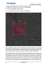
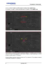
IC100, IC-SMD MSD3819TX-UQY LFBGA TRAY Main IC


Main  integrated  circuit  IC100's  specifications:  Digital  (DVB-T/C)  and  analog 
broadcasting demodulator, USB recording, Broadcast and A/V d(NTSC/PAL/SECAM) 
Full HD 100Hz support, MPEG-2 and MPEG-4 support, 32-Bit Linux based processor, 
Sound and subwoofer processor and interface, 2 USB, 4 HDMI, 2 DDR3 RAM.  


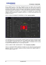
Main integrated circuit collects and processes data coming from all inputs and sends 
audio and video output to the speaker over amplifier and to the panel over LVDS line. 
This  integrated  circuit  has  more  than  500  legs.  Special  equipment  is  required  for 
installation  and  removal. Therefore,  these  integrated  circuits are designed  with  very 
low error ratios. If you suspect any error with main IC on TV, firstly supplies of this 
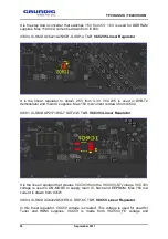
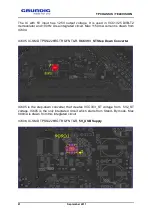
IC  should  be  checked.  There  are  4  input  supplies  as  3.3V,  2.5V,  1.05V  and  1.5V. 
Extremely  low  or  high  ratings  of  these  supplies  might  cause  image  freezing,  some 

Содержание 40VLE630BH

Страница 1: ...TP CHASSIS TELEVISION 1 September 2011 TP CHASSIS TELEVISION SERVICE MANUAL_V2 ...

Страница 2: ... USB Recording USB PVR 12 3 3 10 DIGI LINK and HDMI CEC Feature 12 3 3 11 Operation with Common Interface CI 12 4 PRODUCT INSTALLATION 14 4 1 Product Installation 14 4 2 Input Output Connections 16 4 3 Remote Control 18 4 3 1 Arçelik BEKO Remote Control YB1 YB9 3D 18 4 3 2 GRUNDIG Remote Control TP3 19 4 3 3 GRUNDIG 3D Remote Control TP7 20 4 3 4 GRUNDIG 3D Remote Control TP8 TP9 21 5 USING NEW PR...

Страница 3: ...1 Selecting internet applications 32 5 4 2 Inter ctive browser main menu 33 5 5 DLNA Home Network Connection 33 5 5 1 Selecting Digital Media Server 34 5 6 vTuner Internet radio 34 5 7 USB Functions 35 5 7 1 Recording TV Programmes PVR 35 5 7 2 Time Shift Pause Programme 36 5 7 3 USB Mode 36 5 7 4 Connecting External Data Storage Devices 37 5 7 5 DivX VOD 37 5 8 DIGILINK CEC 37 6 EXTERNAL DEVICE C...

Страница 4: ...S 90 14 SOFTWARE UPDATE 102 14 1 Updating TV Software via USB Memory 102 14 2 BOOT Code Installation From Service Menu via USB Memory 103 14 3 MBOOT Installation via DEBUG TOOL 104 15 SUPPORTED RESOLUTIONS 109 15 1 PC DVI Resolution Info 109 15 2 HDMI H PC Resolution Info 109 15 3 HDMI H YPbPr Resolution Info 110 16 HOTEL TV SETUP 111 17 TP CHASSIS DIGITURK ENABLED TV SETUP 113 17 1 Television set...

Страница 5: ...esign Application 2 1 Notes for satellite are added 02 11 2011 TV Design Application 3 1 Oscilloscope waveforms added 02 11 2011 TV Design Application 4 2 Instruction for software installation updated 14 11 2011 TV Design Application 5 6 7 8 9 10 11 12 13 14 15 16 17 18 19 20 21 22 23 24 25 26 27 28 29 30 31 32 33 34 35 36 37 38 39 40 41 42 43 44 45 46 ...

Страница 6: ...perature and humidity changes Sudden changes of temperature and humidity may harm the panel 5 High temperature and humidity shortens product life LCD and LED panels are not suitable for use under high temperature and humidity conditions The user should observe the stated values of temperature and humidity 6 Keep it away from harmful corrosive gases Corrosive gases damage chemical and electronic st...

Страница 7: ...andard Optic Out Standard DVB T C Standard DVB S2 Optional DISEQC Diseqc 1 2 DVB T2 Optional HDMI CEC Standard CI Standard MPEG4 Standard SRS TruSurround HD MEGA DCR Optional MEMC Standard USB PVR Standard HOTEL TV Optional Basic WI FI Internal External 55 External Other Internal WI FI ETHERNET Standard WEB Standard Internet Applications Optional Facebook Twitter Picasa Flickr Youtube Vtuner DLNA ...

Страница 8: ...asting DVB C Digital video broadcasting cable and digital satellite broadcasting DVB S2 Digital video broadcasting satellite Our TP chassis televisions support DVB T C DVB T2 optional and DVB S2 optional broadcasting Digital receiver unit of the product processes signals coming from digital transmitters and convert them into audio and video of superior quality It enables you to access video music ...

Страница 9: ...Full HD 100Hz 200Hz panel support HDCP Playing picture music and film from USB Dolby Digital Plus High Efficiency Advanced Audio Codec 4 HDMI connection inputs CI Slot input 8 day EPG Electronic Programme Guide 4 lists of favorite channels in digital and analog mode Updating all system software through on air broadcasting ONLINE SOFTWARE UPDATING THROUGH NETWORK SCART S Video RCA connection inputs...

Страница 10: ...s can be accessed by cable or wireless connection 3 3 2 vTuner internet radio Many radio stations broadcast over Internet vTuner provides access to many popular radio worldwide Thanks to the vTuner function of your television you can display a list of radio stations and listen to the stations you like 3 3 3 DLNA Home Network Digital Living Network Alliance DLNA is an association established by the...

Страница 11: ... viewing experience in the comfort of your home 3 3 6 DVB S2 In our TP chassis product satellite dish input is integrated there is not any separate satellite module Thus you can watch satellite broadcasting directly from TV without any satellite receiver box DVB S Digital Video Broadcast Satellite is satellite broadcasting received via dish antenna we have been using for years DVB S2 technology al...

Страница 12: ...programmes as well as TimeShift function can only be carried out by using an external data medium hard drive or USB stick The data medium must have a capacity of at least 2 GB 3 3 10 DIGI LINK and HDMI CEC Feature Our products with TP chassis are equipped with HDMI CEC feature This feature utilizes CEC Consumer Electronics Control protocol CEC allows you to make an HDMI connection between your TV ...

Страница 13: ...TP CHASSIS TELEVISION 13 September 2011 card must be inserted in the CA module to enable the scrambled channels you want to view ...

Страница 14: ...d or 2a For terrestrial digital stations DVB T plug the cable of the rooftop or indoor antenna passive or active indoor antenna with its own power supply into ANT IN socket on the television set or 2b for digital stations of the cable TV network DVB C plug the antenna cable into ANT IN socket on the television set or 2c for analogue stations plug the antenna cable into ANT IN socket on the televis...

Страница 15: ...out of 0 C 40 C range Do not use it in areas close to bathtub sink pool or in humid circumstances such as basements or directly under rain The product should be connected to a grounded socket which is being protected by a fuse complying with the values indicated in the Technical specifications table Our company shall not be liable for the damages that may arise when the product is used before ensu...

Страница 16: ...PONENT Y Pb Pr Video signal input YUV signal L R Audio signal input YUV signal Optic Out Audio output sockets optical for PCM AC3 signals For connecting to a digital multi channel audio video amplifier or AV receiver AUDIO OUT L R Audio output Audio Audio signal input for PC PC IN VGA socket video signal input for PC SATELLITE Satellite dish socket ANT IN Antenna socket HDMI2 HDMI socket audio vid...

Страница 17: ... HDD USB hard disk socket for external data media and PVR function LAN Network cable connection socket U Headphone connection 3 5 mm jack AV2 Video signal input for camcorder L R Audio signal input for camcorder USB1 USB socket for external data media and PVR function HDMI1 HDMI socket audio video signal input HDMI CI Common Interface slot ...

Страница 18: ...ith no USB inserted 16 9 Picture format selection button Picture and teletext PAT button SWAP REPEAT Switching back to the last viewed channel button Teletext sub page Sub button In USB and PVR mode repeat mode selection button M Button to enter and exit menu Source menu button Programme forward backward buttons Volume Down Up buttons Menu up down navigation buttons Menu right left navigation butt...

Страница 19: ...TP CHASSIS TELEVISION 19 September 2011 4 3 2 GRUNDIG Remote Control TP3 ...

Страница 20: ...TP CHASSIS TELEVISION 20 September 2011 4 3 3 GRUNDIG 3D Remote Control TP7 ...

Страница 21: ...TP CHASSIS TELEVISION 21 September 2011 4 3 4 GRUNDIG 3D Remote Control TP8 TP9 ...

Страница 22: ...LE appears 5 1 2 Advanced Installation if you want to receive the stations from a different satellite you must configure the antenna settings satellite LNB Type DISEqC Mode LNB selection for the desired satellite 1 In Source Setup menu Connection type tab select Satellite with 2 Select Advanced Installation with and press OK ANTENNA SETTINGS menu will be displayed 3 Select Auto Tuning with and pre...

Страница 23: ...on stations received The search ends when the PROGRAM TABLE appears If a second satellite is set perform the following steps to set other television channels Press M to open the menu Select SOURCE SETUP with and press OK Then select AUTOMATIC CHANNEL SEARCH with D C and press OK In Select Satellite tab press OK and select the satellite with or Press Red to start searching Repeat other settings sta...

Страница 24: ...tellite channels If a certain channel can not be found with automatic search you can search it manually with manual search function You must enter all parameters of the channel correctly You can obtain the current transponder information from teletext page satellite TV magazines or internet 1 Press M 2 Select SOURCE SETUP with and press OK SOURCE SETUP menu will be displayed 3 Select Digital Manua...

Страница 25: ...sitions 5 2 3D Function 5 2 1 3D Picture Viewing 3D function is only supported at HDMI YPbPr VGA USB DLNA DVB T DVB C and DVB S inputs With HDMI YPbPr and VGA inputs 3D mode is not active except resolutions at 1280x720p 50 60 Hz 1920x1080i 50 60 Hz and 1920x1080p 24 30 50 60 Hz 3D experience may change depending on the format and features of the picture resolution sharpness and etc supplied from t...

Страница 26: ...re activated 2 Select 3D Perspective with V or Λ and adjust with or 3 Select Depth with V or Λ and select the picture setting as Low Medium or High with or 4 Press i to end the setting 5 2 4 Left Right Correction When Frame Packing mode is enabled in HDMI source 3D perception may disappear in 3D films or 3D games due to a synchronization shift arising from HDMI signal You may correct 3D perception...

Страница 27: ...red network connection connect the output of external modem to LAN socket by using a Cat5 cable 5 3 2 Wired Network Settings There are two ways of making the wired network settings A In auto connection all data regarding connection settings IP Address Netmask Gateway and DNS are obtained from modem automatically B In manual connection all data regarding connection settings IP Address Netmask Gatew...

Страница 28: ...s a Static IP address you must enter the IP Address Netmask Gateway and DNS values manually You can obtain your IP Address Netmask Gateway and DNS values from your Internet Service Provider ISP 1 Open the menu with i button 2 Select NETWORK APPS menu with V or Λ and confirm with NETWORK APPS menu will be displayed 3 Select Connection Type option with V or Λ and select Wired with and 4 Select Netwo...

Страница 29: ...xcept for Access Point Selection B In manual connection all data regarding connection settings IP Address Netmask Gateway and DNS should be manually configured 5 3 7 Auto Wireless Network Connection Most of the home networks are Dynamic networks If you have a dynamic network you must use a DSL modem that supports DHCP Modems and IP sharers that support DHCP obtain the DNS values required for IP Ad...

Страница 30: ...t the network connection is established with the current settings Testing Please wait message will be displayed and if it is connected successfully Connection to Gateway Success Internet Connection Success message will be displayed 10 Press i to end the setting Note If you do not have a dynamic network follow the instructions in manual connection section 5 3 8 Manual Wireless Network Connection Ce...

Страница 31: ...ay address with 1 0 and press green to save the value 11 Select DNS with V and press Enter DNS address with 1 0 and press green to save the value 12 Select Connect with red button to establish the modem connection Connecting Please wait message will be displayed 13 Press green button to make sure that the network connection is established with the current settings Testing Please wait message will ...

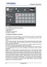
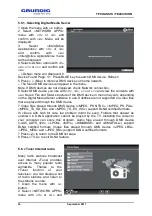
Страница 32: ...peti Viewster no DRM Sahibinden Flixter AMS Funspot Trip Advisor HRS ibb 5 4 1 Selecting internet applications 1 Open the menu with i button 2 Select NETWORK APPS menu with V or Λ and confirm with Menu will be displayed 3 Select Inter ctive Applications with V or Λ and confirm with Inter ctive Applications menu will be displayed 4 Select the application you like with V Λ or and confirm with The ap...

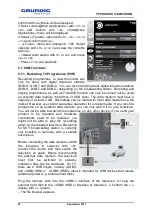
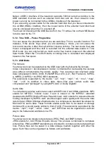
Страница 33: ...yback TV can also operate with DMS software that can be installed on a computer but it is not guaranteed that it will run in full compatibility with software without a DMS certificate Perform the following steps for a sample DMS set up Open Windows Media Player11 i on a computer with Windows operating system In Library tab select Media Sharing On the pop up window check Share my media and press OK...

Страница 34: ...are not supported on video files that are played through the DMS device 7 Video files played through DMS device MPEG_PS_NTSC MPEG_PS_PAL MPEG_TS_SD_EU and MPEG_TS_EU_ISO support DLNA certified formats In videos with high bit rate lag problem might be seen Folders that appear as unknown in DLNA application cannot be played by the TV Installing the codec to your computer can solve this problem Audio...

Страница 35: ...data mediums on the market However we cannot guarantee operation for all data media If you record a programme on an external data medium you can only watch it on your television You will not be able to watch this programme on any other device If you send your product to be repaired and hardware components need to be replaced you might not be able to play the recordings again on the repaired televi...

Страница 36: ... intended for decreasing the storage area without compromising the picture quality Your television can playback video data compressed in DIVX XVID H 264 MPEG 4 AVC L4 1 Ref Frames 4 MPEG 4 MPEG 2 MPEG 1 MJPEG MOV standards File extensions supported by the device avi mkv mp4 ts mov mpg dat vob In addition to video data these files also contain audio data compressed and packaged by using MP3 AAC or ...

Страница 37: ... hard drive digital camera card reader or MP3 player using a USB cable or insert the memory stick in USB1 socket of television 2 Confirm the display with green The file browser appears 5 7 5 DivX VOD DivX is a digital picture format created by DivX Inc This is a DivX Certified device that plays DivX video For more information to convert your files to DivX image files and for software tools please ...

Страница 38: ...ce is connected to your television must be on Selecting menu language When you select menu language on your TV menu language of the external device will change as well If your DVD player supports Switching off the device from standby mode After switching your television to standby your external device e g DVD player will also switch to standby if it is switched on ...

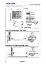
Страница 39: ...al equipment via SCART socket Rear view of product or or GAME CONSOLE SATELLITE RECEIVER GAME CONSOLE SATELLITE RECEIVER Connecting external equipment via AV sockets Side view of product GAME CONSOLE Side view of product SATELLITE RECEIVER Connecting external equipment via S Video socket ...

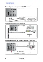
Страница 40: ...roduct GAME CONSOLE Audio connection Video connection Connecting external equipment via HDMI socket SATELLITE RECEIVER Rear and side view of product Connecting digital amplifier AV receiver via Optical Out or SPDIF socket Optical Connection SPDIF Amplifier Rear and side view of product DIGITAL AMPLIFIER ...

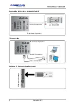
Страница 41: ...ptember 2011 Connecting AV receiver via Audio Out L R Audio Connection Rear view of product AV RECEIVER PC connection Rear view of product Audio Connection Video connection Inserting CI Common Interface card Side view of product ...

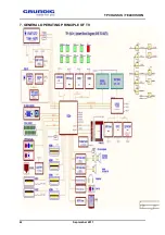
Страница 42: ...TP CHASSIS TELEVISION 42 September 2011 7 GENERAL OPERATING PRINCIPLE OF TV ...

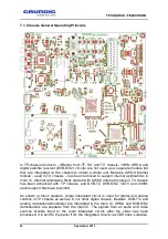
Страница 43: ...started with AWOX internet module in TX chassis has been advanced with TP chassis and DVB T2 DVB S S2 3DTV and 200Hz panel support has been provided As shown in block diagram single integrated circuit is used for digital and analog controls in TP chassis as well as in our other digital chassis Besides DVB T C and analog modulator demodulator are integrated in the main IC URSA and DVB S S2 demodula...

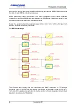
Страница 44: ...on EEPROMs RAMs are used for the processes performed within the integrated circuit Surely the system should be supplied power in 5V 3 3V 1 8V 1 05V 2 5V and 1 2V which is required for these processes 7 2 DC Power Stage The Chassis and supply unit are connected via S605 connector In TP chassis products only 5V is fed from the supply unit PSU in Stand By mode 5V2_ST 12V and 24V supplies are switched...

Страница 45: ...consumption In TP chassis products Stand By power consumption is 0 5W POWER_SW signal sent from the main IC makes the device exit Stand By mode With POWER_SW signal 12V and 24V voltages of PSU are turned on firstly IC608 VCC1V05 IC starts to give output on the chassis and makes POWER GOOD PG signal step in to start other regulators operation With PG signal PG1 is created and with PG1 signal PG2 is...

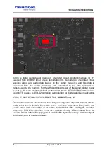
Страница 46: ...essor and interface 2 USB 4 HDMI 2 DDR3 RAM Main integrated circuit collects and processes data coming from all inputs and sends audio and video output to the speaker over amplifier and to the panel over LVDS line This integrated circuit has more than 500 legs Special equipment is required for installation and removal Therefore these integrated circuits are designed with very low error ratios If y...

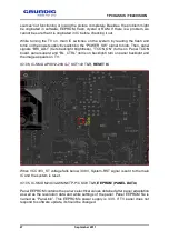
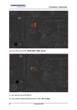
Страница 47: ...acklight brightness TCON_ON turns on Panel TCON board panel supply and BL_CTRL turns on backlight turn on panel backlight and the image appears on TV IC106 IC SMD APX812 29UG 7 SOT143 T R RESET IC When VCC3V3_ST voltage falls below 3 08V System RST signal is sent to the main IC and the system is reset IC105 IC SMD M24C32 WMN6TP P C SO8 T R EEPROM PANEL DATA Panel EEPROM contains the panel s electr...

Страница 48: ...TP CHASSIS TELEVISION 48 September 2011 IC104 OPS AT24C32D EEPROM PANEL DATA It is an optional panel EEPROM IC108 IC SMD W25Q16BVSSIG SOIC8 T R SPI FLASH ...

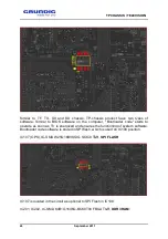
Страница 49: ...r Bootloader code starts to operate as soon as TV is energized and ensures the functioning of system software Bootloader code software is stored in SPI flash which is used on IC108 position IC107 OPS IC SMD W25Q16BVSSIG SOIC8 T R SPI FLASH IC107 is located in the circuit as optional to SPI Flash in IC108 IC201 IC202 IC SMD K4B1G1646G BCK0T00 FBGA T R DDR3 RAM ...

Страница 50: ...coding image and video resolution in all applications Similar to a calculator it constantly carries out the processes to ensure the operation of TV RAM supplies should be carefully checked Fluctuations in RAM supplies may cause various errors Sudden rise or fall of RAM supply might freeze the television and cause picture lagging ...

Страница 51: ...T R NAND Flash Flash memory is where the system operating software is installed It can be inserted into IC101 and IC102 positions on the circuit However only 1GBit flash on IC101 position is being used in TP chassis System software starts to operate as soon as TV is turned on This software installed in the flash controls all TV functions ...

Страница 52: ...a problem in flash IC or it could not be started due to a problem in main IC IC501 IC SMD STA339BWTR POWERSSO 36 T R Audio Amplifier The integrated circuit of audio amplifier amplifies digital audio data coming from main IC to the desired level and sends it out TP chassis audio output is 2x10W IC501 audio amplifier is supplied by 24V VCC_AUDIO voltage A dedicated circuit is used to avoid POP NOISE...

Страница 53: ... T R Subwoofer Amplifier TP chassis products optionally have subwoofer feature IC503 ensures that audio signal sent by main IC is switched amplified and transferred to subwoofer Subwoofer audio output power is 10W IC304 IC SMD MSB1231 LF LQFP64 DATE 1051 TRAY DVBT2 Demodulator ...

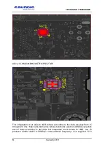
Страница 54: ...BT2 should be selected ON in service menu in addition to lineup of DVBT2 modulator and peripheral components on the chassis DVB T2 demodulator s supplies are 1 3V and 3 3V IC304 communicates with main IC and tuner through I2C lines IC303 IC SMD W25X10BVSNIG SOIC8 T R DVBT2 SPI Flash It is the integrated circuit where the software running DVB T2 processor is installed It is supplied with VCC3V3 vol...

Страница 55: ... main integrated circuit as transport stream STV0903BAC demodulator used in TP chassis is DVB S2 compliant demodulator for digital satellite broadcasting IC306 IC SMD STV6110AT VFQFPN32 T R DVBS2 Tuner IC The satellite receiver tuner obtains inter frequency signal of digital broadcast similar to the tuner in our chassis filters this carrier frequency from other frequencies and sends video and audi...

Страница 56: ...t adjusts LNB voltage according to the data received from IC through I2C line High band low band vertical horizontal selection DiSEqC selection are all done according to the data this integrated circuit sends to LNB Leg 13 produces 22kHz which is DiSEqC communication frequency It is supplied 12 V ...

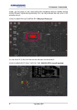
Страница 57: ... in satellite module and as Enable signal when generating 3 3V we may estimate that any error in 12V will affect this IC IC302 IC SMD IP101ALF LQFP48 TRY Ethernet Processor It is the driver IC of the port that ensures ethernet communication IC308 IC SMD AP2171WG 7 SOT23 5 T R VCC3V3_ETH Linear Regulator ...

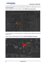
Страница 58: ...es supply for Ethernet IC Max 200mA current is drawn from IC308 IC402 IC SMD AP2171WG 7 SOT23 5 T R PCMCIA Current Limiting It is the integrated circuit that switches VCC PCMCIA supply voltage and limits the current to 1A IC600 IC SMD TPS54226RGTR QFN T R VCC1V5 Step Down Converter ...

Страница 59: ...lator and main IC supplies Max 150 mA current is drawn from IC602 IC601 IC SMD AP2171WG 7 SOT23 5 T R VCC3V3 Linear Regulator It is the linear regulator that creates VCC3V3 from the VCC3V3 ST voltage VCC3V3 voltage is used in ON MODE to supply main IC flash and EEPROM Max 700 mA current is drawn from IC601 IC603 IC SMD XC6222D501ER G USP 6C T R VCC5V Linear Regulator In this linear regulator VCC5V...

Страница 60: ...TP CHASSIS TELEVISION 60 September 2011 VCC5V3_FE is made from VCC12V supply For tuner max 300 mA is drawn from IC603 IC604 IC SMD TPS54226RGTR QFN T R 1V25 Step Down Converter ...

Страница 61: ...rcuit Max 1150 mA current is drawn from IC604 IC605 IC SMD TPS54226RGTR QFN T R VCC3V3_ST Step Down Converter IC605 is the step down converter that creates VCC3V3_ST voltage from 5V2_ST voltage IC605 is the only integrated circuit which starts from Stand By mode Max 800mA is drawn from this integrated circuit IC606 IC SMD TPS54226RGTR QFN T R 5V_USB Supply ...

Страница 62: ...supply voltage for USBs from VCC12V voltage Max 2000mA current is drawn from IC606 IC607 IC SMD AP2151WG 7 SOT23 5 T R USB driver IC IC607 is the USB driver and current limiting IC The current drawn from this IC is limited to 1000 mA IC608 IC SMD TPS54226RGTR QFN T R VCC1V05 Step down converter ...

Страница 63: ... main IC supply Typically 160 mA current is drawn from this IC IC609 IC SMD AP2171WG 7 SOT23 5 T R USB Driver IC Rear USB IC609 serves as current limiting and supply integrated circuit for USB 1000 mA nominal current can be drawn from this integrated circuit IC610 IC SMD AP2171WG 7 SOT23 5 T R USB Driver IC Optional ...

Страница 64: ...tegrated circuit This integrated circuit limits the current to 1000 mA This integrated circuit is placed in the products with Wi fi feature IC614 IC SMD USB2412 DZK TR QFN28 T R It is Internal WI FI driver integrated circuit IC700 IC701 IC703 IC704 IC SMD CAT24C02TDI GT3A TSOT23 5 T R ...

Страница 65: ...TP CHASSIS TELEVISION 65 September 2011 ...

Страница 66: ...01 IC703 and IC704 are also used for the inputs of HDMI1 2 3 and HDMI4 This EEPROM also contains HDMI resolution info and protection password for HDCP or HD broadcast copy In case of failure copy protected HD broadcasting cannot be received IC800 IC SMD MST7398R LF LFBGA TRAY In 100Hz products in addition to main chassis there are also MST7338P integrated circuit 1 RAM of this IC 1 flash crystal a...

Страница 67: ...oftware is located in Ursa folder in the Target folder This software is used by MST7338P For 100Hz integrated circuit there is also 1 optional EEPROM location but it is not being used IC801 IC SMD K4B1G1646G BCK0T00 FBGA T R As explained above RAM is the part that undertakes the processing load of actual integrated circuit To this end 100Hz integrated circuit has to process constantly to convert 5...

Страница 68: ...ntegrated circuit IC802 OPS IC SMD W25Q80BVSSIG IC802 is placed in the circuit as optional to URSA flash in IC804 position IC900 IC SMD MAX9728AETC T R IC900 is the audio amplifier used to strengthen scart audio output signal IC901 IC SMD CAT24C02TDI GT3A TSOT23 5 T R ...

Страница 69: ...supported picture format The broadcasts other than this resolution for example 720P may not be shown Besides IC901 contains EDID DATA information where resolution data of TV and PC connected from VGA input are compared IC902 IC SMD MAX9728AETC T R It is the audio amplifier used to increase Chich connectors audio output TU400 TUN HYB TDAG8 D11A DIK IEC ALPS Tuner ...

Страница 70: ...ification that is calculated by main IC Leg 2 Tuner is locked to the desired channel by communicating with main board and main IC depending on the selected source through I2CT2_SCL and I2CT2_SDA lines It selects the desired frequency by filtering other frequencies and transforms the signal as to enter main IC This chassis does not have a separate demodulator IC Demodulation is performed in main IC...

Страница 71: ...or BEKO ARÇELİK brand TVs For GRUNDIG brand we enter 8 5 0 0 As the chassis improvement and development works go on throughout the production service menu items may vary according to the software version The following explanations are service menu settings of the current version System Configuration This menu contains general settings of the system Press OK button on the remote control to access t...

Страница 72: ... Plug Play tab after servicing After pressing right key on the tab EEPROMs will be loaded with factory defaults TV can be shipped to the customer after this setting Please note that any warning is not displayed or you do not have to exit the menu while Plug Play is getting activated You should be careful not to take the device into Plug Play mode by mistake ATS Auto Service Numbering feature ensur...

Страница 73: ... system broadcasting is initially decoded on CI card The broadcasting transmitted to the main IC from the CI card is also encrypted and it is decoded with CI Key which is a factory setting and different for each TV Thus there will be no free encrypted broadcasting on the bare line and encrypted broadcasting cannot be copied CI feature is standard in all the products with TP chassis SOURCE Configur...

Страница 74: ...ion For Grundig products Grundig is selected This selection adds Grundig next to the user menu and remote control selection is TP3 In Grundig 3D products remote control can be select TP3 TP3_3D TP7 TP8 and TP9 depending on enclosure type and product specifications In Beko and Arçelik the remote control is automatically selected as YB1187R and in 3D products it is YB1187R 3D in addition to several ...

Страница 75: ...e socket on TV In TP chassis headphone should be selected ON as standard SHOP MODE is used in the first installation at the dealers for purposes of display Shop Mode and Home Mode screens appear When Shop Mode is selected the logos of various features such as CI SRS etc which are supported on TV appear on top of screen with certain intervals SHOP MODE should be selected ON for all products However...

Страница 76: ... copy your selections channel lists user options satellite settings and service menu settings on TV and move them to another TV Particularly when installing TV at the user s home this feature will save us time as we will not have to tune satellite channels anew Cloning can be done from any TV with the same chassis To enter this menu you need to go to Cloner configuration from the service menu and ...

Страница 77: ...Video Set section should be copied After copying picture settings of TV may show some differences TV should be delivered to the customer after those settings are checked On User menu go to Source Settings Program Table don t select Press the keys 4 6 5 8 and cloning menu will be displayed Bootcode Configuration In the products with TP chassis Boot code should be updated before software updating Bo...

Страница 78: ...ing on options in the existing cabinets the options have been adjusted to prevent cabinet resonance and ensure best audio quality Software Version All versions of software and hardware can be seen under software version tab URSA version tab is the 100Hz software version installed on 100Hz TVs This menu is for information only it cannot be changed OPTIONAL LOGOS represent the logos to be displayed ...

Страница 79: ...ARD CI STANDARD 3D TV OPTIONAL DLNA Wifi STANDARD Internet TV STANDARD Dolby Digital Plus STANDARD Divx HD STANDARD Picture Perfect Plus 50 Hz panel 100 Hz 100 Hz HD ready LED panel or 100 Hz LCD panel 200 Hz 200 Hz HD ready LED panel or 200 Hz LCD panel ...

Страница 80: ...11 HD 100 Hz 1080p 100 Hz Full HD LED panel HD 200 Hz 1080p 200 Hz Full HD LED panel HD LCD HD Ready panel HD 1080p LCD Full HD panel LED TV LED panel USB Recording STANDARD USB Connectivity STANDARD HDMI STANDARD DVD N A DVB T C STANDARD ...

Страница 81: ...eptember 2011 DVB T2 C OPTIONAL HD Triple Tuner STANDARD HD Triple Tuner T2 OPTIONAL APPROVED LOGOS The logos below are displayed if approved by test results Cable Ready YouSee UPC Ziggo MediaSet France HD Comhem Spain TDT Stofa ...

Страница 82: ... command Thus the features other than the blue highlighted come with the values identified on software as a standard The values of each feature are shown in the next column of the table The values of optional features are stated in VTF Version Demand Form depending on the customer s demand If flash IC is required to be changed in TP chassis products for any reason at the service centre relevant se...

Страница 83: ... Not to be set AVAIL YPbPr AVAIL STD S VHS Not to be set AVAIL SCART AVAIL STD DVD Not to be set AVAIL NAVAIL TUMER Not to be set ALPS A S STD DVBT2 To be set VTF ON OPT OSD SELECTION To be set VTF GRUNDİG OPT USB RECORDING Not to be set ON ON STD REMOTE CONTROL To be set VTF TP3 OPT KEYPAD Not to be set 6 BUTTON 1STD 6 BUTTON 1STD STD L Not to be set ON ON STD MEMC Not to be set ON ON STD 7 SEGME...

Страница 84: ...s supply is not available on L615 check for 12V on the S605 socket s pin 11 If 12V supply is not found on S605 socket although POWER_SW signal exists PSU should be replaced If POWER_SW signal is not available main IC and peripheral components should be checked If VCC_PANEL voltage is found in T603 Leg 2 but not found in Leg 3 T603 and peripheral components are checked When TV is ON a voltage aroun...

Страница 85: ...erter This control is provided with BL_CTRL Besides voltage level that determines brightness of panel lights through Pin 6 of connector S605 should be higher than 3V Brightness control may vary according to the panel however it operates dimly around 0V and completely on around 3 3V Brightness control is done by BRI_ADJ signal coming from the main integrated circuit When the backlighting tab is dim...

Страница 86: ...f the amplifier should be checked for 3 3V DC voltage We should suspect about main integrated circuit if there is no 3 3V This voltage drops down to 0V and ensures switching the amplifier off in Stand By mode AMP_STB signal and main integrated circuit performs the control Sound amplifier has I2C communication lines to communicate with the main integrated circuit Roughly the voltage level should be...

Страница 87: ...TP CHASSIS TELEVISION 87 September 2011 12 FAILURE FLOW TROUBLESHOOTING DIAGRAMS 12 1 Sound but no picture and backlight illuminated ...

Страница 88: ...TP CHASSIS TELEVISION 88 September 2011 12 2 Sound but no picture and backlight not illuminated ...

Страница 89: ...TP CHASSIS TELEVISION 89 September 2011 12 3 No Sound ...

Страница 90: ...TP CHASSIS TELEVISION 90 September 2011 13 CHASSIS DIAGRAMS ...

Страница 91: ...TP CHASSIS TELEVISION 91 September 2011 ...

Страница 92: ...TP CHASSIS TELEVISION 92 September 2011 ...

Страница 93: ...TP CHASSIS TELEVISION 93 September 2011 ...

Страница 94: ...TP CHASSIS TELEVISION 94 September 2011 ...

Страница 95: ...TP CHASSIS TELEVISION 95 September 2011 ...

Страница 96: ...TP CHASSIS TELEVISION 96 September 2011 ...

Страница 97: ...TP CHASSIS TELEVISION 97 September 2011 ...

Страница 98: ...TP CHASSIS TELEVISION 98 September 2011 ...

Страница 99: ...TP CHASSIS TELEVISION 99 September 2011 ...

Страница 100: ...TP CHASSIS TELEVISION 100 September 2011 ...

Страница 101: ...TP CHASSIS TELEVISION 101 September 2011 ...

Страница 102: ...der available in the system according to product code First copy Target folder to USB main directory Before starting installation you should check script and panel files in the Target folder which will be installed The content of Target folder to be transferred to USB disk main directory should be as shown below The content of BIN_FILES folder should be as shown below ...

Страница 103: ...y of the keypad on TV and plug the TV Hold down any key of the keypad on TV until you see that code installation has started USB update logo will be shown on the screen during software download from USB If code installation has been successfully completed TV will automatically turn on Shut down TV to remove the USB 14 2 BOOT Code Installation From Service Menu via USB Memory Boot code update can b...

Страница 104: ...ght key If TV s boot code is not updated Fail message appears next to Start Loading menu item If update is successful TV automatically restart TV should never be shut down during code loading If TV is shut down boot code should be installed by using Debug tool 14 3 MBOOT Installation via DEBUG TOOL This feature should be used when you encounter an error while loading boot code from USB MBoot progr...

Страница 105: ...t is used for PC connection To load MBoot on TV VGA cable is connected to VGA connector that is in the opposite of USB connector Software installation adapter has a key This key enables you to select the pin configuration pin 11 4 the key should be positioned on the USB connector side ...

Страница 106: ...e been loaded on the PC ISP Utility is copied anywhere on the computer and ISP_Tool v4 5 2 8 SP exe application is executed When executed for the first time the program is opened as shown below Settings should be selected as in the figure Under Read press Read button to show the location of software to be installed ...

Страница 107: ...it might be suspected that there is a problem Verify process is a must If there is an error in writing process most probably this will be shown within the first 4 5 seconds you may press Stop button before waiting for the completion of Verify process If the installation is successful Pass message appears TV should be delivered to the customer after completing software installation performing servi...

Страница 108: ...installation TV s service menu settings user customer settings channel list and satellite settings should be stored in an external USB memory device by means of USB cloning feature USB cloning TV to USB and these settings should be re loaded on the relevant TV after software installation USB cloning USB to TV To enter this menu you need to go to Cloner configuration from the service menu and enter...

Страница 109: ...TP CHASSIS TELEVISION 109 September 2011 15 SUPPORTED RESOLUTIONS 15 1 PC DVI Resolution Info Resolutions that can be used with computer connection 15 2 HDMI H PC Resolution Info ...

Страница 110: ...ELEVISION 110 September 2011 15 3 HDMI H YPbPr Resolution Info Resolutions 480i 60Hz 480p 60Hz 576i 50Hz 576p 50Hz 720p 50Hz 720p 60Hz 1080i 50Hz 1080i 60Hz 1080p 24fps 1080p 25fps 1080p 30fps 1080p 50Hz 1080p 60Hz ...

Страница 111: ...sage Hotel TV is intended to prevent hotel guests from changing TV s channel settings and turning volume up to disturbing levels for the environment Therefore Source Settings tab is not shown in user menu We should open Hotel Admin menu to make source settings and determine the highest volume that the user is allowed Picture settings Hotel TV Settings ...

Страница 112: ...e it was turned off at admin mode This feature should be used to set TV s opening channel As an opening channel you may set the hotel s own advertisement channel with hotel s videos or a channel advertising paid broadcasts In customer mode it is not an error that TV is turned on at the same source and channel whichever channel or source was open when turning off the TV You should consider this iss...

Страница 113: ...17 1 Television setup Once TV s mains and satellite antenna connection is completed Installation Guide appears on the screen when the TV is turned on for the first time In the first screen Turkish is selected for language And after selecting Home Mode in the second screen and Turkey in the third screen you should select satellite for Connection Type via joystick in the fourth screen As this is Dig...

Страница 114: ... CA Module Irdeto CA Status Digital Card Status we should see serial number of the Smart card as well as Card Inserted message in Status tab If the card is inserted incorrectly or if it is broken the information on this menu may be missing After this check please select CA Module CAM Management CAM Info and check CAM software and hardware Any missing or irrelevant information indicates that CAM mo...

Страница 115: ...ems you should determine if the problem rests in Digiturk broadcasting or the current installation If there is any problem on the installation broadcasting quality or level In case of a problem in signal level caused by the use of long cable In line amplifier may be attached on headend systems where analog and digital broadcasts VHF UHF IF are provided through the same cable diplexer may be attach...

Страница 116: ... the Smart card as well as Card Inserted message in Status tab If the card is inserted incorrectly or if it is broken the information on this menu may be missing After this check please select CA Module CAM Management CAM Info and check CAM software and hardware Any missing or irrelevant information indicates that CAM module is faulty ...

Страница 117: ...er lists change in time or new ones are added In TP chassis products even though new transponder lists are added in updated software this list may lose validity in time If manual search is performed with the information about newly added or changing frequencies the channels will be found out and added to the end of the list As a solution Turksat satellite has a Turksat Auto Search and Teletext cha...

Страница 118: ...TP CHASSIS TELEVISION 118 September 2011 19 SIGNIFICANT OSCILLOSCOPE OUTPUTS ...

Страница 119: ...TP CHASSIS TELEVISION 119 September 2011 ...

Страница 120: ...TP CHASSIS TELEVISION 120 September 2011 ...

Страница 121: ...LVDS TTL Parallel Flash up to 1Gbit NAND PCMCIA DSP Audio Amp USB1 HDMI2 DVB T C T2 HDMI USB2 0 RGB CVBS SPI Flash PCMCIA CI Tuner ALPS DVB T C T2 TS_OUT SIF 50 60Hz CCFL LED Line Out E2PROM3 I2C I2S 32kBit 8Mbit I2C address at A8 IF V_SAW S_SAW VIF DIF I2CT USB2 HDMI3 HDMI HDMI4 HDMI HDMI1 HDMI I2C I2C address at C0 8 16 Ohm 10W 1Gbit DDR3 I2C UART SPI Flash 8Mbit E2PROM4 32kbit Panel data I2C ad...

Страница 122: ......

Страница 123: ......

Страница 124: ......

Страница 125: ...assis these areas may be corrupted or may overheat the material in this case the power of television should be disconnected 6 When the receiver is not being used for a long time of period of time unplug the power cord of the adaptor from the AC outlet 7 While television is working out do not try to unplug cable or equipment on it 8 With wet hands or wet materials should not be repaired 9 During th...

Страница 126: ...humidity change can make dew or ice which cause nonconformance such as malfunction 5 High temperature high humidity reduce the life time LCD and LED modules are not proper to be used at high temperature and high humidity Please keep specified temperature and humidity condition 6 Keep out of Corrosive Gas Corrosive gas effect the polarizer and the circuit chemically and cause defects accordingly 7 ...

Страница 127: ...are the mboot bin software folder should be copied into the USB memory If more than one partition in memory you should copy into first partition Step 3 Insert the USB memory USB port side of the TV Step 4 Wait USB memory 10 second to mount itself Step 5 Open the Service Menu Step 6 On the Service Menu access the Boot Code Configuration choice and press the OK button Step 7 In case of absence of an...

Страница 128: ...device should be connected the TV s VGA input and PC s USB port There is the need to download driver for this device for Windows XP Do not install drivers for windows 7 Automatic driver installation should be provided for Windows 7 Step 2 ISP_Tool_v4 4 9 9 exe program or a higher version should be run on a PC ISP_Tool_v4 4 9 9 exe s settings are as follows ...

Страница 129: ...s and Device Type is Winb25Q16 message appears on the form Now 16 02 2011 at the project of TF SPI Flash is Winbond If ISP tool finds a diffrent type of flash do not take this into consideration and repeat this step Step 4 Running on the PC on the ISP Tool exe press the Read button and select the bootloader file eg mboot_TF_V08_SAMSUNG_DDR bin given in the software package ...

Страница 130: ...t all the steps Note Making a connection problem may occur during Step 3 With the help of past experience it is observed that connecting possibility increases when the TV s power is cut after TV is re issued 2 Loading TV Software Note Before installing software under the target script usb_auto_update_50Hz txt and usb_auto_update_100Hz txt folders are located According to panel s 50Hz or 100Hz feat...

Страница 131: ...ond Step 5 If the software is installed smoothly the TV will be opened with the new software automatically b Software installation with the help of the ISP Tool Initial Condition Not important Step 1 Given with software package Target folder should be copied without any changes into the USB memory Step 2 Insert the USB memory to the USB port that is located side of the TV Step 3 After MStar ISP to...

Страница 132: ...he statement is written about the presence of plugged memory Step 6 In the console with entering MStar ustar loading is started Step 7 If the installation is successful the TV automatically opens with the new software 3 Download the files related to the panel a Panel bin loading 2K During the installation the settings for 26AU26 panel are installed as a default If Panel bin is wanted to be install...

Страница 133: ...USB memory Step 3 Insert the USB memory to the USB port that is located side of the TV Step 4 After MStar ISP tool connects to the TV a terminal control program such as minicom or hyperterminal is executed Settings Baud 115200 Databits 8 Stopbits 1 Parity None FlowControl None Step 5 TV power off changed to power on Within 1 second immediately with pressing PC s ENTER key TV s drop to the console ...

Страница 134: ...r re is entered or directly with making power off on to the TV opening TV is provided b Panel bin loading 4K During the installation the settings for 26AU26 panel are installed as a default If Panel bin is wanted to be installed for another panel Step 1 In the software package desired panel file in the RELEASED_PANEL_FILES folder is copied under the Target BEKO_BIN_FILES panel folder and file s na...

Страница 135: ...fter MStar ISP tool connects to the TV a terminal control program such as minicom or hyperterminal is executed Settings Baud 115200 Databits 8 Stopbits 1 Parity None FlowControl None Step 5 TV power off changed to power on Within 1 second immediately with pressing PC s ENTER key TV s drop to the console is provided Step 6 In the console MStar usb start 1 is entered ...

Страница 136: ...sole MStar re is entered or directly with making power off on to the TV opening TV is provided c Loading gamma information Step 1 In the software package panel file in the RELEASED_PANEL_FILES folder GAMMA bin is copied under the Target BEKO_BIN_FILES panel folder Step 2 Until Step 7 steps followed to Panel bin also followed for GAMMA bin When the time is coming to the Step 7 with entering to the ...

Страница 137: ...ading HDCP Key Step 1 In the software package panel file in the RELEASED_PANEL_FILES folder HDCP bin is copied under the Target BEKO_BIN_FILES panel folder Step 2 Until Step 7 steps followed to Panel bin also followed for HDCP bin When the time is coming to the Step 7 with entering to the console MStar ustar eprom_hdcp loading is started Step 3 After installation is completed in the console ...

Страница 138: ...ursa bin is copied under the Target BEKO_BIN_FILES panel folder Step 2 Until Step 7 steps followed to Panel bin also followed for ursa bin When the time is coming to the Step 7 with entering to the console MStar ustar ursa loading is started Step 3 After installation is completed in the console MStar re is entered or directly with making power off on to the TV opening TV is provided ...

Страница 139: ...ite cable is getting out of the TV set and moves the TV set away from the wall or satellite cable input is too deep to plug the cable The satellite cable is touching the wall which leads to customer dissatisfaction SOLUTION A new L satellite cable connector is added to our lists with the code 038086R and an instruction manual with the code VSG813 With best regards ...

Страница 140: ...ss facebook However in the SW versions V01 22 V01 28 and V01 31 this address is written as tv grundig com fb When the user enters this address to his web browser on the PC he gets the message This webpage is not available Internet Explorer cannot display the webpage etc and cannot use facebook application CAUSE Server failure In the future both addresses will be valid SOLUTION Within the SW versio...

Страница 141: ...reen may be shown scattered and 3D perception is limited SOLUTION Please refer to the following instructions 1 Please go to PICTURE SETTINGS 2 Please go to 3D Settings 3 Then make 3D Mode 2D 3D 4 Please select Effect Mode as ON 5 Please make appropriate adjustments on 3D Perspective and Depth according to the broadcast Note There is no default settings related with 3D Perspective and Depth it depe...

Страница 142: ...a special broadcast over satellite In some cases TV may crash and TV does not start up from standby SOLUTION TV can start to work again by updating the software with a special version Please download this special software from http www grundig de software tv html and update the TV set by USB using usual SW Update Procedure Note that update of this special SW may take longer than a usual SW update ...

Страница 143: ...terminate broadcasting Second of all some digital channels will be added and some will change broadcasting transponder Below you can find the precautions for chassis SX TX TF and TP Arçelik and Grundig have taken for our customers to have minimum dissatisfaction due to this change SOLUTION We are offering two solutions for minimum customer dissatisfaction 1 The end users will make another search w...

Страница 144: ...SW version will show the chassis type The set in the picture have TP chassis o Or from the back cover the chassis type will be written in another sticker Picture 2 Software Version Screen Picture 3 TV Back Cover Sticker Then the user shall go to Grundig s webpage www grundig de to download the clone file prepared for his her TV chassis And the end user shall put that clone file to his her USB stic...

Страница 145: ...ing the adjustments like in the picture the user shall press to the red button to clone the program list After cloning the list the user is going to have the program table that Grundig have prepared The end user shall not make another automatic search More detailed information about how to do take these actions are shown in a video in the commercial channel of Grundig Deutschland in Youtube http w...

Страница 146: ...SIS TP SUBJECT 3D doesn t work PROBLEM With TP chassis 3D products 3D feature is not working which is caused by VSF170 VTV170 VTZ170 coded 3D emmiter modules SOLUTION In 3D emmiter module please replace the component at D1 position with 302334R LED 5MM 850NM INFRARED 1 5V Best Regards ...

Страница 147: ... in DVB T channels after connecting the external wi fi dongle SOLUTION Please follow the steps below 1 Remove the back cover 2 Use an EMI tape 10x30mm part nr VX6391 AR to connect a USB s S603 metal case and side metal case in shortest way as shown in the attached pic b HDMI S703 metal case and side metal in shortest way as shown in the attached pic 3 Close the back cover and screw it 4 Insert the...

Страница 148: ...TP chassis altough there is the Internet connection there is no connection to YouTube application Besides other Interactive TV applications are properly connected and succeeded in operating SOLUTION Please update the bootcode version as BOOT TP V01 012 00 or current version and main SW version as TPGRMR V03 020 00 or current version of the TV set With Best Regards ...

Страница 149: ...the RC PROBLEM When frequently pushing a button especially MUTE button on the remote control in some cases related with the existence of the electronic devices in medium there may occur of changing over of the TV from ON mode into Stand By mode SOLUTION Please update SW version of the TV as TPGRMR V04 004 00 or current SW version With Best Regards ...

Страница 150: ...R V05 004 00 and using it on the products whose SW version is TPGRMR V05 004 00 newer one leads to deletion of channel list SOLUTION Due to a database change in V5 x software channel list from V4 x software cannot be cloned The channel list cloning should be made among the products whose SW version is older than TPGRMR V05 004 00 or among the products whose SW version is TPGRMR V05 004 00 newer on...

Страница 151: ... part number has also been changed Recently ordered subwoofer boxes will not be compatible with existing woofer cables on the TV set SOLUTION While ordering subwoofer boxes one should use the new part numbers and should add the corresponding cable part number to the order as shown on the table below Old Part Nr New Part Nr New Cable Part Nr KLK228 VNT228R VWY506R VNT228 VNT228R VWY506R VTY228 VNT2...

Страница 152: ...are version 04 004 00 P P buttons changes channels on main list until version 05 005 00 These buttons are not to be used for skipping channels through FAV list SOLUTION P P buttons will function as opening FAV list pop up effective from software 05 005 00 In FAV list end user may select desired channel using navigation buttons on the remote and push OK to open that channel Next page shows an illus...

Страница 153: ...ist end user presses P or P button on the remote This launches FAV list popup Step 2 On the FAV list desired channel could be selected using navigation buttons on the remote Step 3 TV will switch to the selected channel by pressing OK button on the remote ...

Страница 154: ...TP Chassis SUBJECT Connecting trouble with Reuters Application PROBLEM Due to application change Reuters application will not be accessible SOLUTION With the next online SW update Reuters application will be removed and more extensive Euronews application will take place With best regards ...

Страница 155: ... PAIC1020H8 PAIC1020J3 PAIC1020J4 PAIC1020J5 PAIC1020J6 PAIC1020J7 PAIC1020J8 PAIC1020K3 PAIC1020K4 PAIC1020K5 PAIC1020K6 PAIC1020K7 PAIC1020K8 PAIC1020L1 PAIC1020L2 PAIC1020L9 PAIC1020L10 PAIC1020M1 PAIC1020M2 PAIC1020M9 PAIC1020M10 COIC102 PAIC10304 PAIC10303 PAIC10302 PAIC10301 COIC103 PAIC10405 PAIC10404 PAIC10403 PAIC10402 PAIC10401 COIC104 PAIC10507 PAIC10505 PAIC10508 PAIC10501 PAIC10502 PA...

Страница 156: ...A T P 1 8 7 0 1 COTP187 P A T P 1 8 8 0 1 COTP188 P A T P 1 8 9 0 1 COTP189 P A T P 1 9 0 0 1 COTP190 P A T P 1 9 1 0 1 COTP191 P A T P 1 9 2 0 1 COTP192 P A T P 1 9 3 0 1 COTP193 P A T P 1 9 4 0 1 COTP194 P A T P 1 9 5 0 1 COTP195 PATP19601 COTP196 P A T P 1 9 7 0 1 COTP197 P A T P 1 9 8 0 1 COTP198 P A T P 1 9 9 0 1 COTP199 P A T P 2 0 0 0 1 COTP200 P A T P 2 0 1 0 1 COTP201 P A T P 2 0 2 0 1 CO...

Страница 157: ...2 PAIC60301 PAIC60307 COIC603 PAIC60401 PAIC60402PAIC60403 PAIC60405 PAIC60406 PAIC60407 PAIC60408 PAIC60409 PAIC604010 PAIC604011 PAIC604012 PAIC604013 PAIC604014 PAIC604015 PAIC604016 PAIC604017 PAIC60404 COIC604 PAIC60504 PAIC605017 PAIC605016 PAIC605015 PAIC605014 PAIC605013 PAIC605012 PAIC605011 PAIC605010 PAIC60509 PAIC60508 PAIC60507 PAIC60506 PAIC60505 PAIC60503 PAIC60502 PAIC60501 COIC605...

Страница 158: ...C60301 PAIC60307 COIC603 PAIC60401 PAIC60402PAIC60403 PAIC60405 PAIC60406 PAIC60407 PAIC60408 PAIC60409 PAIC604010 PAIC604011 PAIC604012 PAIC604013 PAIC604014 PAIC604015 PAIC604016 PAIC604017 PAIC60404 COIC604 PAIC60504 PAIC605017 PAIC605016 PAIC605015 PAIC605014 PAIC605013 PAIC605012 PAIC605011 PAIC605010 PAIC60509 PAIC60508 PAIC60507 PAIC60506 PAIC60505 PAIC60503 PAIC60502 PAIC60501 COIC605 PAIC...

Страница 159: ...60301 PAIC60307 COIC603 PAIC60401 PAIC60402PAIC60403 PAIC60405 PAIC60406 PAIC60407 PAIC60408 PAIC60409 PAIC604010 PAIC604011 PAIC604012 PAIC604013 PAIC604014 PAIC604015 PAIC604016 PAIC604017 PAIC60404 COIC604 PAIC60504 PAIC605017 PAIC605016 PAIC605015 PAIC605014 PAIC605013 PAIC605012 PAIC605011 PAIC605010 PAIC60509 PAIC60508 PAIC60507 PAIC60506 PAIC60505 PAIC60503 PAIC60502 PAIC60501 COIC605 PAIC6...

Страница 160: ...IC60301 PAIC60307 COIC603 PAIC60401 PAIC60402PAIC60403 PAIC60405 PAIC60406 PAIC60407 PAIC60408 PAIC60409 PAIC604010 PAIC604011 PAIC604012 PAIC604013 PAIC604014 PAIC604015 PAIC604016 PAIC604017 PAIC60404 COIC604 PAIC60504 PAIC605017 PAIC605016 PAIC605015 PAIC605014 PAIC605013 PAIC605012 PAIC605011 PAIC605010 PAIC60509 PAIC60508 PAIC60507 PAIC60506 PAIC60505 PAIC60503 PAIC60502 PAIC60501 COIC605 PAI...

Страница 161: ...IIC1000T15 PIIC1000T16 PIIC1000T17 PIIC1000T18 PIIC1000U7 PIIC1000U8 PIIC1000U9 PIIC1000U10 PIIC1000U11 PIIC1000U12 PIIC1000U13 PIIC1000U14 PIIC1000U15 PIIC1000U16 PIIC1000U17 PIIC1000U18 PIIC1000V7 PIIC1000V8 PIIC1000V9 PIIC1000V10 PIIC1000V11 PIIC1000V12 PIIC1000V13 PIIC1000V14 PIIC1000V15 PIIC1000V16 PIIC1000V17 PIIC1000V18 PIIC1000W7 PIIC1000Y6 PIIC1000Y7 COIC100F PIIC10101 PIIC10102 PIIC10103...

Страница 162: ...IC2020K1 PIIC2020K2 PIIC2020K3 PIIC2020K7 PIIC2020K8 PIIC2020K9 PIIC2020L1 PIIC2020L2 PIIC2020L3 PIIC2020L7 PIIC2020L8 PIIC2020L9 PIIC2020M1 PIIC2020M2 PIIC2020M3 PIIC2020M7 PIIC2020M8 PIIC2020M9 PIIC2020N1 PIIC2020N2 PIIC2020N3 PIIC2020N7 PIIC2020N8 PIIC2020N9 PIIC2020P1 PIIC2020P2 PIIC2020P3 PIIC2020P7 PIIC2020P8 PIIC2020P9 PIIC2020R1 PIIC2020R2 PIIC2020R3 PIIC2020R7 PIIC2020R8 PIIC2020R9 PIIC20...

Страница 163: ...22 PIIC306023 PIIC306024 PIIC306025 PIIC306026 PIIC306027 PIIC306028 PIIC306029 PIIC306030 PIIC306031 PIIC306032 PIIC306033 COIC306 PIIC30701 PIIC30702 PIIC30703 PIIC30704 PIIC30705 PIIC30706 PIIC30707 PIIC30708 PIIC30709 PIIC307010 PIIC307011 COIC307 PIIC30801 PIIC30802 PIIC30803 PIIC30804 PIIC30805 COIC308 PIJ30101 PIJ30102 PIJ30103 PIJ30104 PIJ30105 COJ301 PIL30001 PIL30002 COL300 PIL30101 PIL3...

Страница 164: ...34 PIR43501 PIR43502 COR435 PIR43601 PIR43602 PIR43603 PIR43604 PIR43605 PIR43606 PIR43607 PIR43608 COR436 PIR43701 PIR43702 PIR43703 PIR43704 PIR43705 PIR43706 PIR43707 PIR43708 COR437 PIR43801 PIR43802 COR438 PIR43901 PIR43902 COR439 PIR44001 PIR44002 PIR44003 PIR44004 PIR44005 PIR44006 PIR44007 PIR44008 COR440 PIR44101 PIR44102 COR441 PIR44201 PIR44202 PIR44203 PIR44204 PIR44205 PIR44206 PIR442...

Страница 165: ...003 PIR50004 PIR50005 PIR50006 PIR50007 PIR50008 COR500 PIR50101 PIR50102 PIR50103 PIR50104 PIR50105 PIR50106 PIR50107 PIR50108 COR501 PIR50201 PIR50202 PIR50203 PIR50204 PIR50205 PIR50206 PIR50207 PIR50208 COR502 PIR50301 PIR50302 COR503 PIR50401 PIR50402 COR504 PIR50501 PIR50502 COR505 PIR50601 PIR50602 COR506 PIR50701 PIR50702 COR507 PIR50801 PIR50802 COR508 PIR50901 PIR50902 PIR50903 PIR50904 ...

Страница 166: ... PIR60508 COR605 PIR60601 PIR60602 COR606 PIR60701 PIR60702 COR607 PIR60801 PIR60802 COR608 PIR60901 PIR60902 COR609 PIR61001 PIR61002 COR610 PIR61101 PIR61102 PIR61103 PIR61104 PIR61105 PIR61106 PIR61107 PIR61108 COR611 PIR61201 PIR61202 COR612 PIR61301 PIR61302 COR613 PIR61401 PIR61402 COR614 PIR61501 PIR61502 COR615 PIR61601 PIR61602 PIR61603 PIR61604 PIR61605 PIR61606 PIR61607 PIR61608 COR616 ...

Страница 167: ...72102 PIR72103 PIR72104 PIR72105 PIR72106 PIR72107 PIR72108 COR721 PIR72201 PIR72202 PIR72203 PIR72204 PIR72205 PIR72206 PIR72207 PIR72208 COR722 PIR72301 PIR72302 COR723 PIR72501 PIR72502COR725 PIR72601 PIR72602COR726 PIR72701 PIR72702COR727 PIR72801 PIR72802COR728 PIR72901 PIR72902 COR729 PIR97901 PIR97902 COR979 PIS70001 PIS70002 PIS70003 PIS70004 PIS70005 PIS70006 PIS70007 PIS70008 PIS70009 PI...

Страница 168: ...5702 COR857 PIR85801 PIR85802 COR858 PIR85901 PIR85902 COR859 PIR86001 PIR86002 COR860 PIR86101 PIR86102 COR861 PIR86201 PIR86202 COR862 PIR86301 PIR86302 COR863 PIR86401 PIR86402 PIR86403 PIR86404 PIR86405 PIR86406 PIR86407 PIR86408 COR864 PIR86501 PIR86502 COR865 PIR86601 PIR86602 COR866 PIR86701 PIR86702 PIR86703 PIR86704 PIR86705 PIR86706 PIR86707 PIR86708 COR867 PIR86801 PIR86802 COR868 PIR86...

Страница 169: ...9 PIR96001 PIR96002 COR960 PIR96101 PIR96102 PIR96103 PIR96104 PIR96105 PIR96106 PIR96107 PIR96108 COR961 PIR96201 PIR96202 PIR96203 PIR96204 PIR96205 PIR96206 PIR96207 PIR96208 COR962 PIR96301 PIR96302 PIR96303 PIR96304 PIR96305 PIR96306 PIR96307 PIR96308 COR963 PIR96401 PIR96402 PIR96403 PIR96404 PIR96405 PIR96406 PIR96407 PIR96408 COR964 PIR96501 PIR96502 PIR96503 PIR96504 PIR96505 PIR96506 PIR...

Страница 170: ... R511 C537 R510 C522 C618 T600 R617 R616 C619 L602 S605 R848 R846 C821 C810 C808 R876 R877 R811 1 40 T604 L607 C627 1 C549 C120 C557 19 C667 C662 IC611 R655 R668 C510 C509 R650 C661 D607 1 3 C541 S501 FID2 L614 R651 9 R653 R649 C657 C666 C663 WOOFER S502 R534 C553 C550 C548 C552 R533 R513 C526 C514 C518 C517 C513 R507 B1 S808 HDMI S703 USB S603 S901 S903 Layer T706 C901 R908 C908 SH402 C915 1 R915...

Страница 171: ...80 TP138 TP57 TP10 TP25 TP83 TP46 TP250 TP49 TP254 TP110 TP246 TP114 TP106 TP247 TP256 TP92 TP120 TP122 TP229 TP6 TP130 TP2 TP232 TP102 TP7 TP145 TP207 TP208 TP216 TP225 TP218 TP18 TP193 TP195 TP104 TP51 TP157 TP146 TP159 TP168 TP170 TP53 TP204 TP183 TP184 TP181 TP214 TP56 TP54 TP21 TP257 TP8 TP231 TP234 TP133 TP50 TP26 TP1 TP3 TP4 TP64 TP13 TP140 TP34 TP37 TP23 TP28 TP27 TP24 TP113 TP42 TP244 TP2...

Страница 172: ... AC1 IC100D MSD3819TX_BGA20 2x20 2 C112 100nF C113 100nF D_IF_N D_IF_P L108 0R 0 47uH SPDIF_OUT AUVRM AUVRP AUVAG SPI SCK SPI SDO SPI SDI UART TX UART RX RESET_OUT USB0_P USB0_N System RST USB1_P USB1_N XTALI XTALO SC1 Rin SC1 Lin SC1 HSYNC RF_CTRL FLASH_WPN C SPI CS0N AUDIO Line In MIC Phone Line Out I2S In I2S Out SPDIF AUL0 R4 AUR0 T6 AUL1 T4 AUR1 T5 AUL2 U6 AUR2 U5 AUL3 V6 AUR3 V5 AUL4 V4 AUR4...

Страница 173: ... VDDQ A1 VDDQ A8 VDDQ C1 VDDQ C9 VDDQ D2 VDDQ E9 VDDQ F1 VDDQ H2 VDDQ H9 VSSQ B9 VSSQ B1 VSSQ D1 VSSQ D8 VSSQ E2 VSSQ E8 VSSQ F9 VSSQ G1 VSSQ G9 VDD B2 VDD D9 VDD G7 VDD K2 VDD K8 VDD N1 VDD N9 VDD R1 VDD R9 VSS A9 VSS E1 VSS G8 VSS J2 VSS J8 VSS M1 VSS M9 VSS P1 VSS P9 VSS T1 VSS T9 NC1 J1 NC2 J9 NC3 L1 NC4 L9 NC5 M7 A13 T3 NC7 T7 VSS B3 IC201 DDR3 H5TQ1G63BFR TP18 TP A0 N3 A1 P7 A2 P3 A3 N2 A4 P...

Страница 174: ...1 TS MDI2 TS MDI3 TS MDI4 TS MDI5 TS MDI6 TS MDI7 TS MDI0 TS MDI1 TS MDI2 TS MDI3 TS MDI4 TS MDI5 TS MDI6 TS MDI7 TS MDI0 TS MICLK TS MISYNC TS MIVALID C376 100n C379 100n VCC3V3 VCC3V3 VCC3V3 VCC3V3 VCC3V3 VCC3V3 VCC3V3 VCC3V3 VCC3V3 VCC3V3 VCC3V3_ETH VCC3V3_ETH VCC1V25 C385 NC 47pF C383 NC 47pF DVBT2_RST DVBT2_RST T2_RST R335 100R L319 FB 60R SCLT_1 SDAT_1 VDD_1V0 DVBT2_RST SCL_S2 SDA_S2 VDD_1V0...

Страница 175: ...M_OE_N GPIO113 AC16 PCM_IORD_N CI_RD GPIO111 AA16 PCM_IOWR_N CI_WR GPIO109 AA17 PCM_CE_N CI_CS GPIO115 Y15 PCM_WE_N AB20 PCM_WAIT_N CI_WACK GPIO100 U20 IC100I MSD3819TX_BGA20 2x20 2 PCM RST PCM A8 PCM A9 PCM IOWR PCM A11 PCM A0 PCM A1 PCM A2 PCM A3 PCM A7 PCM A4 PCM A5 PCM A6 PCM WAIT PCM A12 PCM IRQA PCM WE PCM A14 PCM CD PCM A13 PCM REG PCM OE PCM IORD PCM A10 PCM CE PCM_RESET PCM_A12 PCM_A7 PCM...

Страница 176: ...1 220pF C527 100nF C526 100nF C517 100nF C513 100nF C535 100nF C534 100nF C518 100nF C514 100nF C528 220n 50V X7R C519 220n 50V X7R C520 220n 50V X7R C529 220n 50V X7R TP56 R510 2 2R L502 NR6045T220M L503 NR6045T220M L504 NR6045T220M L505 NR6045T220M R520 10k SP_LEFT SP_RIGHT VCC3V3 C511 10u 35V C510 10u 35V C509 10u 35V C512 10u 35V C530 22pF C531 22pF C532 22pF C533 22pF 7 5 3 1 8 6 4 2 R512 100...

Страница 177: ... 100MHz R608 100R NR4018T3R3M L604 3u3 max 950mA for 100Hz R610 6 2K 1 R609 2 7K 1 TP68 max 250mA for DVBT2 C661 10uF C612 100nF C627 10uF R627 2 7K 1 C634 10uF 6V3 C632 10uF 6V3 L607 300R 100MHz R623 100R Hi ON Lo OFF max 2000mA R620 15 4K 1 R619 100 TP82 C625 100nF VCC12V 5V_USB NR6045T3R0N L610 3uH VCC3V3 VCC5V3_FE 5V_USB VFB 1 VREG5 2 SS 3 GND 4 PG 5 EN 6 PGND1 7 PGND2 8 SW1 9 SW2 10 SW3 11 VB...

Страница 178: ...T54CW TP105 TP106 TP107 TP108 TP115 TP116 TP117 TP118 TP124 TP125 TP126 TP127 TP132 TP133 TP134 TP135 TP136 T704 BC847B T706 BC847B T705 BC847B T700 BC847B R710 47k R720 47k R715 47k R702 47k HDMI3 HPDIN HDMI2 HPDIN HDMI1 HPDIN HDMI0 HPDIN HDMI RXACKP G2 RXACKN G1 RXA0P H2 RXA0N G3 RXA1P J2 RXA1N H3 RXA2P J3 RXA2N J1 DDCDA_DA M6 DDCDA_CK L5 HOTPLUGA M5 RXBCKP D2 RXBCKN D1 RXB0P E2 RXB0N D3 RXB1P F...

Страница 179: ... DQSU B7 DMU D3 DQL0 E3 DQL1 F7 DQL2 F2 DQL3 F8 DQL4 H3 DQL5 H8 DQL6 G2 DQL7 H7 DQSL F3 DQSL G3 DML E7 BA0 M2 BA1 N8 BA2 M3 CS L2 RAS J3 CAS K3 WE L3 CK J7 CK K7 CKE K9 ODT K1 RESET T2 VREFCA M8 VREFDQ H1 ZQ L8 VDDQ A1 VDDQ A8 VDDQ C1 VDDQ C9 VDDQ D2 VDDQ E9 VDDQ F1 VDDQ H2 VDDQ H9 VSSQ B9 VSSQ B1 VSSQ D1 VSSQ D8 VSSQ E2 VSSQ E8 VSSQ F9 VSSQ G1 VSSQ G9 VDD B2 VDD D9 VDD G7 VDD K2 VDD K8 VDD N1 VDD...

Страница 180: ...12 47nF C921 220pF C900 47nF R913 2 7K R921 12K C904 330pF C907 47nF R922 12K R904 75R 1 R900 47R C919 1uF C914 47nF C923 100pF R918 75R 1 C924 100pF C920 1uF R919 150R 1 C922 220pF R905 47R R914 75R 1 C906 47nF SC1 R SC1 G SC1 B SC1_CVBS IN SC1 VSYNC SC1 HSYNC SC1 Rin SC1 Lin SC1 C Full SCART VCOM0 R902 47R C902 47nF VCOM0 2 4 6 8 10 12 14 16 18 20 1 3 5 7 9 11 13 15 17 19 21 S900 SCART SC1_Lout ...

Отзывы: