


When flow calculation is enabled, it typically takes around 10 pump
cycles before a flow is presented in the main screen. These pump
cycles are used to learn the inflow variations, if any. Note that the
learning has to be initiated manually in this menu if variable speed
is used. In all other cases, it is done automatically.
When power usage and flow values are also available, the
controller can calculate the specific energy which is the kW usage
to pump a known amount of water, like kW/m
3
. This is very useful
information for the costumer, as it indicates the running condition of
the pump. When monitored over time with a SCADA system, the
costumer sees that the specific energy rises. This is due to wear
and tear of the pump. There could also be a dramatic change in the
specific energy, which could indicate a pipe leak, a defective
seal, etc. This is very useful, as it can enable the costumer to do
preventive maintenance.
Example of a configuration:
•
An analog level sensor has been detected, and flow calculation
is available.
•
A pressure sensor on discharge has been detected, which
improves precision.
•
Pit depth is set to 5 m, which means that the range of the level
sensor has been chosen to be 0-5 meters (information coming
from the AI configuration).
•
Upper measurement level is set to 1.45 m (this level must be
lower than "Start level 1").
•
Lower measurement level is set to 0.50 m (this must be higher
than "Stop level").
•
Pit area is set to 0.2 m
2
(this is calculated by measuring the
diameter of the pit and multiplying it by Phi).
•
Calculation delay is set to 5 seconds, allowing the pump to get
up to speed. It is important to set the delay correctly if VFD
or soft starter is used, and there is a certain ramp-up time
involved.
The level sensor is shown in the display as mounted in a pipe. The
message here is that it is important that the level sensor is fixed in
the pit, not allowing it to move around as this would affect the level
measurement. A pit with a mixer causes a lot of turbulence that
moves the sensor around in the pit if it is not secured.
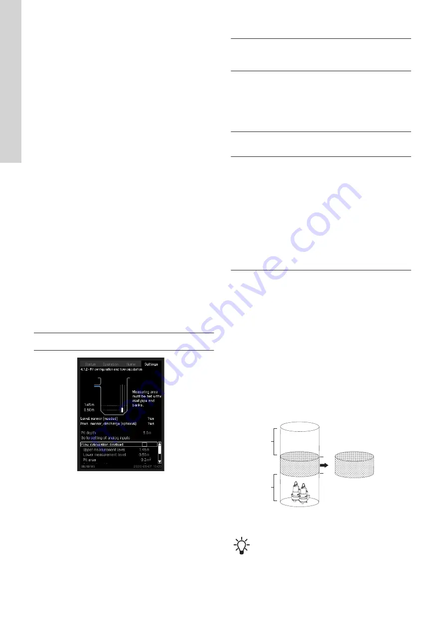
Path: Settings > Basic functions > Pit configuration and flow
calculation
TM078592
Pit configuration and flow calculation
Display text
Upper measurement
level
Enter the upper measurement level used for
the flow calculation. It must be lower
than "Start level 1" and below the inlet pipe
of the pit.
Lower measurement
level
Enter the lower measurement level used for
the flow calculation. It must be above "Stop
level" and above any banks in the pit, and if
possible, also above the pumps as they
have an influence on the volume when the
level goes down to where the pumps are.
But most importantly, it must be set
above "Stop level".
Pit area
Enter the surface area of the pit. This is
done by measuring the diameter of the pit
and multiplying it by Phi.
Measurement delay
Enter a time that allows the pump to ramp
up before the flow calculation is
started. The factory setting is 5 seconds,
but with a direct-on-line or star-delta
controlled pump it can be lowered to 2-3
seconds.
Be aware of the ramp-up time, especially
with a soft starter or VFD controlled pump.
The flow calculation must not start before
the pumps run at full speed.
Also be aware of any mechanical or
electrical flush valves that are used during
pump start-up. The measurement delay
must allow the valve to close before starting
the flow calculation.
For the best result, it is important to allow the flow calculation to be
active as long as possible. This means that the difference
between the upper and lower levels should be as big as possible,
and the measurement delay should be as low as possible.
In pits where the inflow is placed very low in the pit, and the
distance down to the stop level is limited, and consequently the time
of emptying the pit is very short, it can be difficult for the controller
to calculate the flow. If the controller does not show a flow in the
main screen after at least 10 pump cycles, check whether the
settings match the physical conditions in the pit.
Related information
8.1.2.1 Flow calculation, theory
8.1.2.1 Flow calculation, theory
Start
Stop
h2
h1
Volume
TM028972
Example of pit
The figure above shows an ideal pit.
To obtain optimum flow calculation, the following situations must be
taken into account:
•
The pit is not cylindrical.
24
English (GB)


