Groen groen TDBCCE Series Скачать руководство пользователя страница 12

12 OM-TDB/TDBC-CE

Maintenance

NOTICE:   Contact an authorized representative when repairs are required.

A Maintenance & Service Log is provided at the back of this manual. Each time 

maintenance is performed on your kettle, enter the date on which the work was done, 

what was done, and who did it.  Keep this manual on file and available for operators to 

use. Periodic inspection will minimize equipment down time and increase the efficiency 

of operation. The following points should be checked: 

1.  Periodic Maintenance


BY OPERATOR

a. 

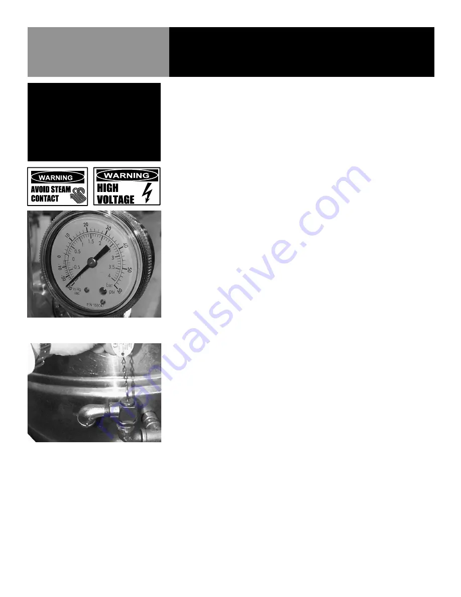
 Check the pressure/vacuum gauge every day. The gauge should show a 

vacuum of 20 to 30 inches of Mercury or a range of -0.7 to -1.0 Bar, when 

the kettle is cold. If it does not, see “Jacket Vacuum” on page 12.

b.   Also check the jacket water level each day. It should be above mid point 

of the round sight glass. If the level is low, see “Jacket Filling and Water 

Treatment” on page 13.


BY SERVICE TECHNICIAN

c.   Test the safety valve at least twice each month. Test the valve with the kettle 

operating at 15 PSI (1 Bar/105 kPa), by pulling up the test chain for at least 

five seconds. Then release the chain and let the valve snap shut. If the valve 

does not activate, (there is no evidence of discharge, or the valve leaks) 

stop using the kettle immediately and contact a qualified Groen service 

representative.

d.   The inside of the support housing should be kept clean.

e.   At least twice a year, grease the two trunnion bearings. The bearings are 

located within the kettle support housing. Remove the access panels from 

the support housing with a screwdriver to gain access to the grease fittings. 

Use a lithium-based, multi-purpose grease. When the access panels are 

removed, the mounting bolts for the trunnion bearings and tilt switch can also 

be checked for tightness.

f.   On the crank-tilt models, the gear housing has fittings for proper lubrication 

of moving parts. Because the gears do not run in oil, periodic lubrication 

with grease is necessary. Frequency of lubrication will depend on operating 

conditions, but the service should be performed at least once every six 

months.


Add grease through the Zerk fittings on the gear housing until you see 

grease flow out of the bearings around the trunnion shaft. Also place a liberal 

amount of grease on the gear to cover the arc that is in contact with the 

worm gear. When finished, reassemble access panels to support housing.


Electrical wiring should be kept securely connected and in good condition.

2.  Jacket Vacuum


When the kettle is cold, a positive pressure reading or a reading around zero on 

the pressure/vacuum gauge indicates the presence of air in the jacket. Air in the 

jacket slows down the heating of the kettle.


TO REMOVE AIR:

a.   Start the unit. (See the “Operation” section of this manual.) (Be sure there 

is water or product in the kettle when heating).

WARNING
WHEN TESTING, AVOID ANY EXPOSURE TO
THE STEAM BLOWING OUT OF THE SAFETY
VALVE. DIRECT CONTACT COULD RESULT
IN SEVERE BURNS. DISCONNECT ELECTRICAL 
POWER FROM THE KETTLE BEFORE 
ATTEMPTING TO GREASE THE TRUNNION 
BEARINGS.

Test the safety valve at least twice each month.

The pressure gauge should show a vacuum of 

20 to 30 inches when the kettle is cold. 

Содержание groen TDBCCE Series

Страница 1: ...tions thoroughly before installing or servicing this equipment NOTIFY CARRIER OF DAMAGE AT ONCE It is the responsibility of the consignee to inspect the container upon receipt of same and to determine...

Страница 2: ...THE MANUFACTURER ARE NOT TO BE ADJUSTED BY THE INSTALLER BEFORE ATTEMPTING ANY SERVICING ENSURE THAT THE ELECTRICAL SUPPLY IS DISCONNECTED WARNING THE UNIT MUST BE INSTALLED BY PERSONNEL QUALIFIED TO...

Страница 3: ...EPLACING ANY PARTS DISCONNECT THE UNIT FROM THE ELECTRIC POWER SUPPLY WARNING KEEP WATER AND SOLUTIONS OUT OF CONTROLS AND ELECTRICAL EQUIPMENT NEVER SPRAY OR HOSE THE SUPPORT HOUSING OR ELECTRICAL CO...

Страница 4: ...Parts Lists page 19 22 Wiring Diagram page 23 25 Service Log page 26 27 KLENZADE SALES CENTER ECOLAB Inc 370 Wabasha St Paul Minnesota 55102 800 352 5326 or 612 293 2233 NATIONAL FIRE PROTECTION ASSOC...

Страница 5: ...e switch as safety features A heating indicator light pressure gauge and sight glass are provided for monitoring kettle operation A single electrical connection is required for installation The unit m...

Страница 6: ...ion for future reference Space for these entries is provided at the top of the Service Log at the back of this manual Keep this manual on file and available for operators to use When installation is t...

Страница 7: ...the incoming lines A BX connection is not recommended Observe all local and national codes and all regulations in force at the time of installation 5 Confirm that the jacket water level is above mid p...

Страница 8: ...at setting The HEAT amber indicator light should come on immediately and heating should continue until the water boils The HEAT indicator will cycle on and off as the heater elements are cycled under...

Страница 9: ...ank tilt turn the handle The kettle will remain in the position to which tilted until cranked again COMMON ACCESSORIES 1 Lift Off Cover As with stock pot cooking an optional lift off cover can speed u...

Страница 10: ...water to fully drain from product before moving basket away from the kettle Do not rest kettle basket on kettle rim or pouring lip If basket is too heavy for individual to lift and safely move get he...

Страница 11: ...nt the thermostat switch closes the HEAT indicator light comes on the contactors close and the heaters come on again On off cycling continues keeping the kettle at the set temperature This is why the...

Страница 12: ...housing Remove the access panels from the support housing with a screwdriver to gain access to the grease fittings Use a lithium based multi purpose grease When the access panels are removed the mount...

Страница 13: ...tle jacket 4 Water Treatment Procedure a Obtain water treatment compound and a PH test kit from your authorized Groen parts distributor b Fill the mixing container with the measured amount of water re...

Страница 14: ...le continues heating after it reaches the desired temperature User a Thermostat dial setting Authorized Service Rep Only b Thermostat circuit for short X c Thermostat operation The thermostat should c...

Страница 15: ...t purchased has been handcrafted from the finest materials meticulously inspected and carefully tested to ensure that you receive the best possible product With reasonable care and periodic maintenanc...

Страница 16: ...Kettle Prior to operation thoroughly clean the kettle using hot water and detergent Kettle capacities Model Maximum Capacity Recommended Capacity TDB C 20 18 9 liters 16 liters TDB C 24 22 6 liters 1...

Страница 17: ...h limit control will open and shut off power to the elements until the kettle cools Setting the operating thermostat dial to O shuts down the heating circuits Setting the power switch to the OFF posit...

Страница 18: ...plies 200 parts per million available chlorine Obtain advice on sanitizing agents from your supplier of sanitizing products Following the supplier s instructions apply the agent after the unit has bee...

Страница 19: ...ING 1 500 124764 20 WASHER LOCK 3 8 005618 21 SCREW 3 8 16 X 1 HEX HEAD 005612 22 WASHER FLAT 3 8 005830 23 WELDMENT KETTLE BODY 230 240V 20 QT 141353 23 WELDMENT KETTLE BODY 230 240V 40 QT 141355 33...

Страница 20: ...096963 2 THERMOSTAT 012313 3 WATER LEVEL ELECTRODE 015589 4 BRACKET 137736 5 COVER 003141 6 GASKET BOTTOM COVER 137969 7 SCREW 20 X 1 012597 8 GASKET BOTTOM COVER SCREW 137968 9 HEATER JUMPER WIRE 171...

Страница 21: ...Description Part 1 GAUGE COMPOUND PRESSURE W DUAL 084208 2 VALVE PRESSURE RELIEF 50 PSI 1 2 NPT PED 141360 3 ASSY WATER FILL SUB 137438 4 ELBOW 3 4 NPT 90 DEG STREET BRASS 010668 Item not depicted cal...

Страница 22: ...ER INSULATION 003490 12 WASHER SHAKEPROOF LOCK 6 005715 13 NUT HEX 4 40 003121 14 TRANSFORMER 50VA 208 230 V PRI 24 V SEC 148899 15 LUG GROUND 14 6 AWG 129714 16 SCREW 8 32 X 3 8 HEX HD CAP 069789 17...

Страница 23: ...OM TDB TDBC CE 23 Wiring Diagram 400 230 V with Neutral Wye...

Страница 24: ...24 OM TDB TDBC CE Wiring Diagram 240V 3 Phase without Neutral Delta...

Страница 25: ...OM TDB TDBC CE 25 Wiring Diagram 240V 1 Phase without Neutral Delta...

Страница 26: ...26 OM TDB TDBC CE Service Log Model No Purchased From Serial No Location Date Purchased Date Installed Purchase Order No For Service Call Date Maintenance Performed Performed By...

Отзывы: