X
Y
Table
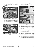
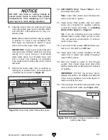
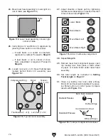
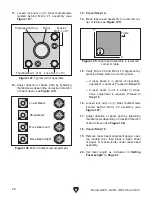
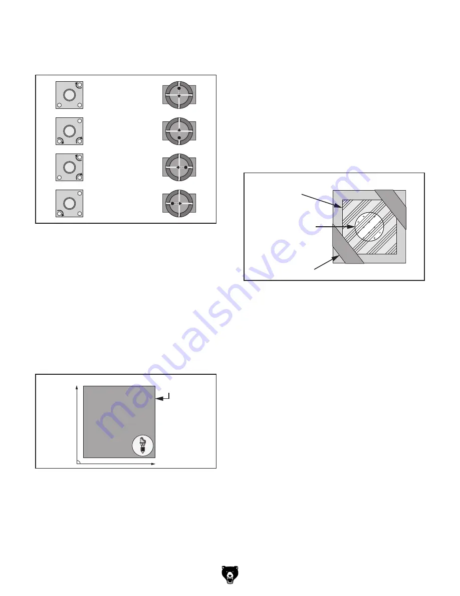
Figure 125. Laser head assembly in lower right
corner of table.
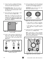
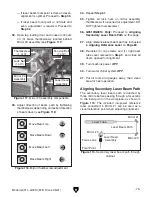
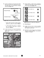
Lower Beam
Raise Beam
Move Beam Left
Move Beam Right
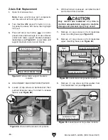
Figure 124. Mirror thumbscrew adjustment.
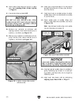
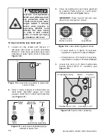
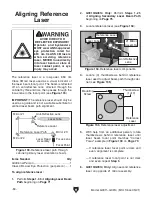
Masking Tape
Mirror
Mirror
Alignment
Gauge
Mirror Assembly
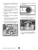
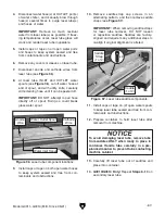
Figure 126. Mirror alignment gauge installed.
Model G0911–G0914 (Mfd. Since 05/21)
-77-
8.
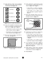
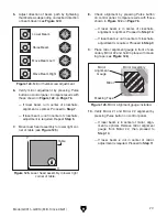
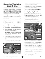
Check alignment by pressing Pulse button
on control panel. Compare results with those
shown in
Figure 122 on Page 76.
— If laser beam is in center of crosshairs,
alignment is optimal. Proceed to
Step 14.
— If laser beam is not in center of crosshairs,
adjustment is required. Proceed to
Step 9.
9. Place mirror alignment gauge in front of sec-
ondary Mirror #2 and hold in place with mask-
ing tape (see
Figure 126).
10.
Verify Mirror #1 and Mirror #2 alignment by
pressing Pulse button on control panel.
— If laser beam is in center of mirror, align-
ment is optimal. Remove mirror alignment
gauge from Mirror #2, then proceed to
Step 14.
— If laser beam is not in center of mirror,
adjustment is required. Proceed to
Step 11.
5. Adjust direction of beam path by tightening
thumbscrews depending on desired direction
of beam travel (see
Figure 124).
6.
Verify mirror adjustment by pressing Pulse
button on control panel. Compare results with
those shown in
Figure 122 on Page 76.
— If laser beam is in center of crosshairs,
alignment is optimal. Proceed to
Step 7.
— If laser beam is not in center of crosshairs,
adjustment is required. Repeat
Step 5.
7. Move laser head assembly to lower right cor-
ner of table (see
Figure 125).
Содержание G0911
Страница 100: ......

