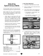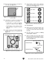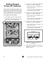
Laser Head Assembly
Front
View
Side
View
Paper
Slot
Mirror #3
Beam Inlet
Paper
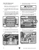
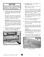
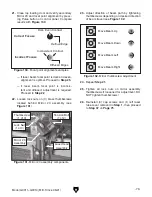
Figure 107. Laser beam alignment gauge
installed in beam inlet.
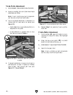
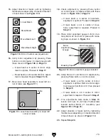
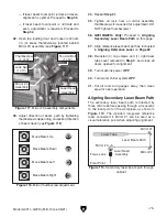
Optimal Laser
Beam Location
Align
Laser Beam
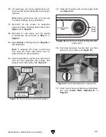
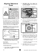
Figure 108. Laser beam alignment marks.
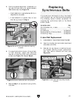
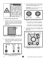
X
Y
Table
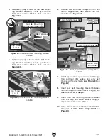
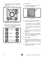
Figure 106. Laser head assembly in upper left
corner of table.
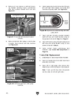
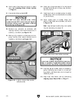
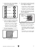
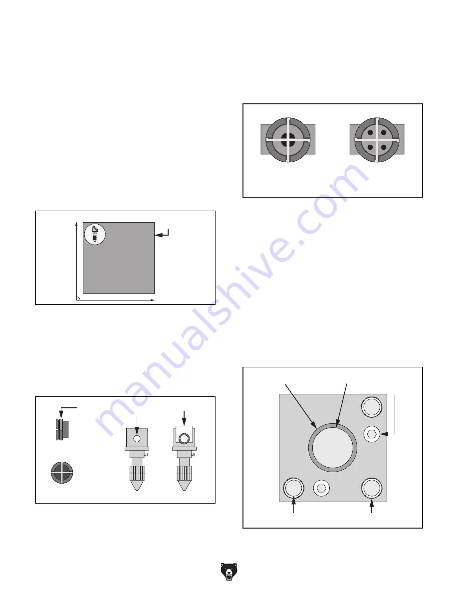
Mirror
Tension
Bolt (1 of 2)
Compression Ring
Thumbscrew (1 of 3)
Lock Nut (1 of 3)
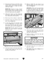
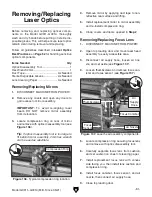
Figure 109. Typical mirror assembly.
-72-
Model G0911–G0914 (Mfd. Since 05/21)
12.
Insert 1" piece of paper or manila folder into
small slot on laser beam alignment gauge
behind wire crosshairs, and install gauge
in beam inlet on laser head assembly (see
Figure 107).
13.
Close top loading door and check alignment
by pressing Pulse button on control panel.
Compare results with
Figure 108 below.
IMPORTANT: Pulse function will only oper-
ate with top loading door closed.
— If laser beam is in center of crosshairs,
alignment is optimal. Proceed to
Step 17.
— If laser beam is not in center of cross-
hairs, adjustment is required. Proceed to
Step 14.
14. Loosen lock nuts on (3) thumbscrews located
behind Mirror #1 (see
Figure 109).
Note: Tension bolts on mirror assemblies
help prevent misalignment during operation.
Always keep moderate tension on tension
bolts when adjusting alignment.
9.
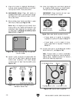
Press Z/U button to highlight "MinPower1",
and use arrow navigation buttons to set mini-
mum power to 50%, then press Enter.
10. G0913/G0914 Only:
Press Z/U button to
highlight "MinPower2", and use arrow naviga-
tion buttons to set minimum power to 50%,
then press Enter.
11.
Move primary laser head assembly to upper
left corner of table (see
Figure 106).
Note:
Steps for aligning the secondary laser
beam path on the Model G0913/G0914 are
performed after aligning the primary path,
as instructed in
Aligning Secondary Laser
Beam Path on Page 75.
Содержание G0911
Страница 100: ......


