
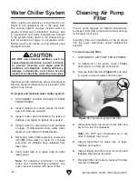


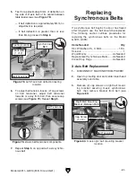

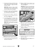

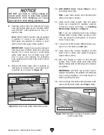

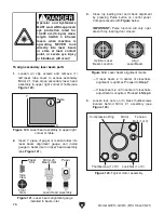
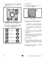

Figure 95. Location of water chiller ports.
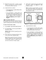
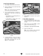
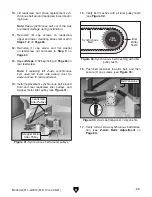
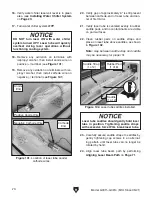
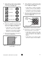
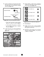
Figure 94. Leadscrew nut measurement.
-66-
Model G0911–G0914 (Mfd. Since 05/21)
Removing/Installing
Laser Tube(s)
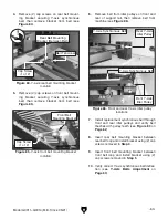
Leveling Table
Each CO
2
gas-filled laser tube is supported by
two soft-mount saddles and straps. Each tube has
four connection points: two for water inlet/outlet
hoses, and two for electrical connections.
The following procedure includes steps required
for the purpose of long-term storage or machine
shipping. If the laser tube has reached the end
of its service life and will be discarded, the tube
should be placed in a container and tagged for
appropriate disposal.
Note: Laser tube removal/installation is the same
on primary and secondary laser tubes.
Items Needed
Qty
Hex Wrenches 2.5, 3mm ..............................1 Ea.
Phillips Head Screwdriver #2 ............................. 1
Utility Knife ......................................................... 1
Bucket ................................................................. 1
Container (for Removed Laser Tube) ................. 1
Isopropyl Alcohol ................................ As Needed
Removing Laser Tube
1. DISCONNECT MACHINE AND AUXILIARY
SYSTEMS FROM POWER!
2. Open laser tube access door.
3.
Disconnect water hose(s) at INLET port(s) of
water chiller, and place end(s) into bucket to
collect water runoff
(see
Figure 95
).
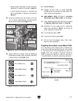
The Model G0911–G0914 table may slowly twist
or drop over time, causing inadequate workpiece
cutting and variations in engraving quality.
Items Needed
Qty
Protective Gloves................................................ 1
Precision Ruler ................................................... 1
To level table:
1. DISCONNECT MACHINE FROM POWER!
2. Verify machine is level (see Leveling on
Page 22).
3. Open front access door and lower side
access door, then measure distance of each
leadscrew nut from bottom of cabinet (see
Figure 94
).
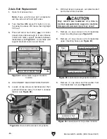
— If measured distance is the same for all
leadscrews, no adjustments are required.
— If measured distance is not the same for
all leadscrews, proceed to
Step 4.
INLET
OUTLET
4. Release Z-axis belt tension on leadscrew(s)
requiring adjustment (see
Step 6
of
Z-Axis
Belts Adjustment
on
Page 61)
.
5.
Grasp irregular leadscrew(s) by hand and
rotate to raise or lower table until
distance
measured in
Step 2
is the same for all
leadscrews
.
6.
Tension Z-axis synchronous belt (see
Step 6
of
Z-Axis Belts Adjustment on Page 61).
Area of
Measurement
Содержание G0911
Страница 100: ......


