


-48-
Model G0853 (Mfd. Since 07/18)
Blade Guard
The term "blade guard" refers to the assembly
shown in
Figure 78.
Understanding & Using Blade Guard
The blade guard MUST be installed on the saw for
all cuts. The guard encloses the top of the blade
to reduce the risk of accidental blade contact and
to contain flying chips or dust. When installed
and properly maintained, it is an excellent tool
for reducing the risk of injury when operating the
table saw.
Sometimes the guard or its components can get
in the way when cutting very narrow workpieces
or performing other specialized cuts. Use the lock
handle shown in
Figure 78 to move the guard
out of the way. The blade guard MUST remain
installed on the saw. If the blade guard is removed
for specific operations, always replace it immedi-
ately after those operations are complete.
As the workpiece is pushed into the blade,
the guard lifts and remains in contact with the
workpiece during the cut, then returns to a resting
position against the table once the workpiece is
pushed completely past the guard.
To ensure that the guard does its job effectively,
it MUST be centered over blade and properly
adjusted so it moves up and down to accommo-
date workpieces and maintain coverage over the
blade after the workpiece exits.
To test blade guard operation, lift the front end
all the way up, then release it. The blade guard
should freely drop down and both wheels should
contact the table surface.
If the blade guard remains in the same position
where you released it, loosen the lock nuts secur-
ing the blade guard to the guard arm, and re-test
operation until the guard freely drops all the way
down.
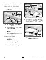
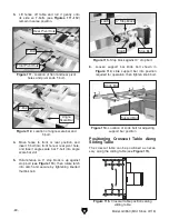
Adjusting Blade Guard
Loosen the hex bolt securing the guard arm (see
Figure 78), and adjust the guard so the distance
between the blade and both guard covers is
equal.
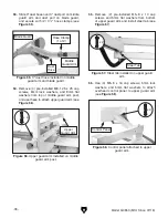
For stock up to 1" thick, loosen the (3) lock nuts
securing the guard to the guard arm (see
Figure
79)
1
⁄
4
-turn each so the blade guard moves
smoothly up and down with the workpiece. For
stock thicker than 1", set the guard to rest on the
workpiece, then tighten the (3) lock nuts.
Figure 78. Blade guard assembly.
Lock Knob
Lock Handle
Guard
Covers
Hex Bolt
IMPORTANT: Every time the blade guard is re-
installed, you must verify that it functions correctly
before making a cut.
Figure 79. Location of blade guard lock nuts.
x 3


