


-32-
Model G0853 (Mfd. Since 07/18)
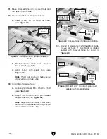
21. On front of leadscrew housing assembly,
locate center pin on rip fence base mounting
bracket (see
Figure 33).
Figure 33. Location of rip fence mounting
bracket.
Center Pin
Mounting
Bracket
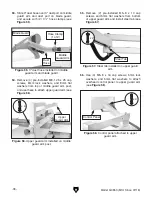
22. Position rip fence base over center pin on
mounting bracket (see
Figure 34) and lower
rip fence base into place. Secure with (2)
M12-1.75 x 30 cap screws and 12mm lock
washers, and install slide lock handle.
23. Install (1) 16mm plastic cap in center pin hole
and (2) 22mm plastic caps over cap screw
holes.
24. Connect rip fence sensor housing wire (see
Figure 35) to matching wire emerging from
rip fence base.
Note: Rip fence sensor housing comes from
the factory pre-wired to the electrical box.
Figure 35. Rip fence sensor wires attached.
Sensor
Housing Wire
Rip Fence
Base Wire
25. Attach rip fence sensor housing (see Figure
36) to rip fence base using (2) pre-installed
M5-.8 x 45 Phillips head screws.
Figure 36. Rip fence sensor housing attached to
rip fence base.
x 2
Release
Housing
Figure 34. Rip fence base mounted on bracket.
Slide Lock
Handle
x 2
Rip Fence
Base


