-20-
Model G0825 (Mfd. Since 02/17)
The guide plate must be adjusted to allow top
edge of edgebanding tape to align flush to top of
workpiece. Use the guide-plate height scale (dis-
played in millimeters) to set the guide plate.
Note: For smooth feeding, add a few millime-
ters to your measurement to allow clearance for
adjustments in
Step 3. This can easily be done
by putting an appropriately thick piece of paper on
workpiece when setting guide plate.
Note: Always ensure guide plate lock is properly
secured before operation.
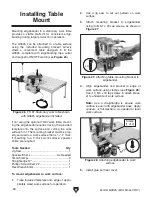
To set height of guide plate:
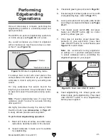
1. Place guide plate on top of workpiece, then
move edgebander toward workpiece until
feed roller and baseplate contact workpiece
edge, as shown in
Figure 17.
Note: If necessary, raise or lower the
guide plate to allow outfeed rollers to reach
workpiece.
2. Retighten guide-plate lock lever to secure
setting.
Guide Plate
Lock Lever
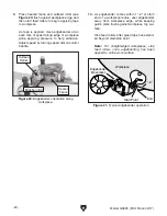
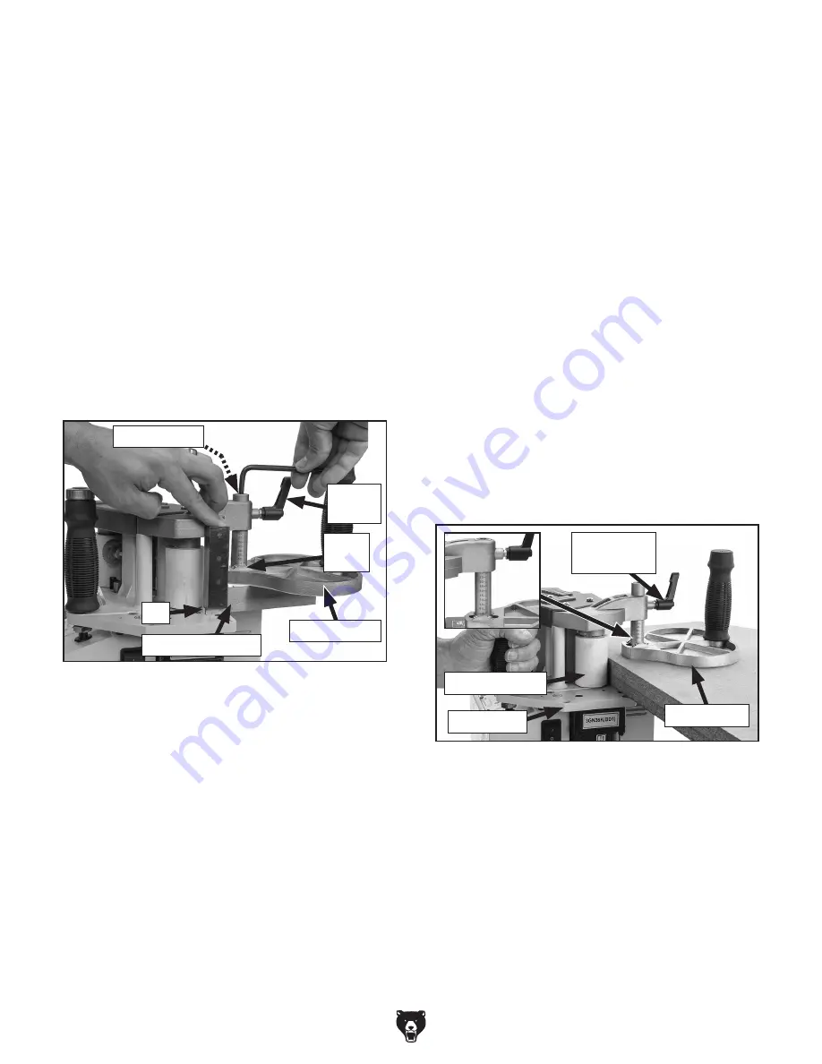
Figure 17. Guide plate adjusted for workpiece
height.
Guide Plate
Outfeed Roller
Base Plate
Setting Guide Plate Height
4. Tighten lock screw and re-check to confirm
setting.
5. Calibrate angle scale pointer/scale plate to 0º
by loosening Phillips head screws, adjusting
scale plate, then retightening screws.
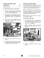
To set guide plate angle 90º to feed roller:
1. With one hand, place precision square even
with face of outfeed roller and across outfeed
side of base plate (see
Figure 16).
2. With free hand, loosen guide-plate lock lever
(see
Figure 16), and lower guide plate evenly
onto precision square, then retighten lock
lever.
3. Loosen lock screw (see Figure 16), and
adjust guide plate angle until it sits flush
along precision square.
Figure 16. Squaring guide plate.
Lock
Lever
Precision Square
Lock Screw
Guide Plate
90º
Angle
Scale
Tools Needed
Qty
Precision Square ............................................... 1
Hex Wrench 6mm .............................................. 1
Setting Guide Plate Angle
Содержание G0825
Страница 44: ......

