9
VersiVent Energy Recovery Ventilator
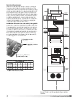
Recommended Roof Opening
Refer to weight and dimension data to determine the
exact location of the section containing the outdoor
air discharge opening. If the unit is equipped with
an Indirect Gas Heater (IG) section, the outdoor air
discharge opening will be in that section; if not, it will
be in the blower section. The return air intake will
be consistent for all units. The dimensions of these
openings and their locations are illustrated below.
When cutting only duct openings, cut opening one inch
(25 mm)
larger than duct size to allow clearance for
installation. Area enclosed by roof curb must comply
with clearance to combustible materials. If the roof is
constructed of combustible materials, area within the
roof curb must be ventilated, left open, or covered with
non-combustible material which has an “R” value of at
least five. If area within curb is open, higher radiated
sound levels may result.
Where the supply or warm air duct passes thru a
combustible roof, a clearance of one inch must be
maintained between the outside edges of the duct
and combustible material in accordance with NFPA
Standard 90A. Position the unit roof opening such that
the supply discharge and exhaust inlet of the unit will
line up with the corresponding ductwork. Be sure to
allow for the recommended service clearances when
positioning opening (see Service Clearances). Do not
face the outdoor air intake of the unit into prevailing
wind and keep the intake away from any other exhaust
fans. Likewise, position the exhaust discharge opening
away from outdoor air intakes of any other equipment.
E
G
H
F
A
B
C
D
Retur
n Air Intake
Supply Air
Discharge
VER-45
A
B
C
D
E
F
G
H
1
56.9
4.7
51.5 15.9 26.9 42.7
3.3
11.8
2
56.9
4.7
51.5 15.9 33.8 34.1
7.4
14.4
3
56.9
4.7
51.5 15.9 33.8 34.1 35.3 14.4
4
56.9
4.7
51.5 15.9 26.9 42.7 31.2 11.8
VER-65
A
B
C
D
E
F
G
H
1
59.9
6.3
56.1 15.9 29.9 51.9
2.7
10.3
2
59.9
6.3
56.1 15.9 30.9 49.9
7.3
7.1
3
59.9
6.3
56.1 15.9 30.9 49.9 35.2
7.1
4
59.9
6.3
56.1 15.9 29.9 51.9 30.6 10.3
VER-90
A
B
C
D
E
F
G
H
1
77.9
4.7
99.2 15.9 33.8 61.9
2.0
12.7
2
77.9
4.7
99.2 15.9 33.8 51.9
7.5
17.7
3
77.9
4.7
99.2 15.9 33.8 51.9 35.3 17.7
4
77.9
4.7
99.2 15.9 33.8 61.9 29.9 12.7
All dimensions are in inches.
IG = Indirect Gas Furnace; PDX = Packaged DX Cooling
1 = Any unit without IG and PDX.
Blower Module is at the end of the unit.
2 = Any unit with IG that does not have PDX.
3 = Any unit with IG and PDX
4 = Any unit without IG and with PDX
Handling
While this unit was constructed with quality and
dependability in mind, damage still may occur during
handling of the unit for installation. Exercise extreme
caution to prevent any damage from occurring to the
refrigerant system. This unit could contain a system
pressurized with refrigerant that, if damaged, could
leak into the atmosphere or cause bodily harm due to
the extreme cold nature of expanding refrigerant. Use
protective equipment such as gloves and safety glasses
to minimize or prevent injury in case of a system leak
during installation.
The system design and installation should follow
accepted industry practice, such as described in
the ASHRAE Handbook. Adequate space should be
left around the unit for piping coils and drains, filter
replacement, and maintenance. Sufficient space should
be provided on the side of the unit for routine service
and component removal should that become necessary.
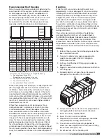
Lifting
1. Before lifting, be sure that all shipping material has
been removed from unit.
2. To assist in determining rigging requirements,
weights are provided in the Unit Weights &
Dimensions section.
3. Unit must be lifted by all lifting lugs provided on
base structure.
4. Rigger to use suitable mating hardware to attach to
unit lifting lugs.
5. Spreader bar(s) must span the unit to prevent
damage to the cabinet by the lift cables.
6. Always test-lift the unit to check for proper balance
and rigging before hoisting to desired location.
7. Never lift units by weatherhoods.
8. Never lift units in windy conditions.
9. Preparation of curb and roof openings should be
completed prior to lifting unit to the roof.
10. Check to be sure that gasketing (supplied by
others) has been applied to the curb prior to lifting
the unit and setting on curb.
11. Do not use fork lifts for handling unit.


