13
VersiVent Energy Recovery Ventilator
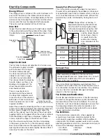
Typical Control Center Components
1. Main Disconnect (non-fusible, lockable)
2. Motor Starter - Exhaust Air Fan
3. Motor Starter - Supply Air Fan
4. Motor Contactor - Energy Wheel
5. 24 VAC Control Transformer
6. 24 VAC Terminal strip
7. Fuses for blower motors*
8. Grounding lug
9. Distributor block*
10. Compressor fuse blocks*
11. Compressor contactors*
12. Condensing fan contactors*
13. Compressor relay*
14. Terminal block*
15. Compressor cycle timers*
Optional Control Center Components
16. DDC controller*
17. Dirty filter pressure switches*
18. Terminal block
19. Energy recovery wheel VFD*
*Not always provided
1
8
7
5
6
18
9
2
3
4
19
17
16
11
12
10
13
15
14
Field-Provided Disconnect
If field-installing an additional disconnect switch, it
is recommended that there is at least four feet of
service room between the switch and system access
panels. When providing or replacing fuses in a fusible
disconnect, use dual element time delay fuses and size
according to the rating plate.
Discharge Air Temperature Sensor
Without Indirect Gas Furnace
For units without an indirect gas furnace, the discharge
air temperature sensor is factory-mounted in the blower
discharge section of the unit behind the blower cut off
plate.
With Indirect Gas Furnace
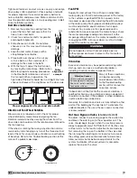
For units with an indirect gas furnace, the discharge
air temperature sensor is to be
field-installed prior to unit start
up at least three duct diameters
downstream of the heat exchanger
or where good mixed average
temperature occurs in the ductwork.
The discharge air sensor is shipped
loose and can be found in the unit’s
control center. See the unit-specific
wiring diagram for connection locations.
WARNING
Discharge air temperature sensor is to be field-
installed prior to unit start-up on units with an indirect
gas furnace.


