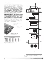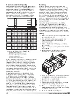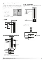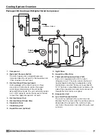
19
VersiVent Energy Recovery Ventilator
Microprocessor Controller
The microprocessor controller is specifically designed
and programmed to optimize the performance of the
unit with supplemental
heating and cooling. This
option ensures that the
outdoor air is conditioned
to the desired discharge
conditions. The controller and accompanying sensors
are factory-mounted, wired and programmed. Default
settings are pre-programmed, but are easily field-
adjustable.
The microprocessor controller can be interfaced with
a Building Management System through LonWorks
®
,
BACnet
®
, or ModBus.
Please refer to the microprocessor controller for energy
recovery Installation, Operation and Maintenance
manual for detailed information.
Unoccupied Recirculation Damper
The unoccupied recirculation option provides a
recirculation damper from the return air intake to the
supply airstream to reduce heating and cooling loads
when less ventilation is required. During the unoccupied
mode, the exhaust fan will remain off and the supply
air fan will operate with mode of tempering to maintain
unoccupied temperature set point.
Service Outlet
120 VAC GFCI service outlet ships loose for field-
installation. Requires separate power source so power
is available when unit main disconnect is turned off for
servicing.
Vapor Tight Lights
Vapor tight lights provide light to each of the
compartments in the energy recovery unit. The lights
are wired to a junction box mounted on the outside of
the unit. The switch to turn the lights on is located in
the unit control center. The switch requires a separate
power source to allow for power to the lights when the
unit main disconnect is off for servicing.
Hot Gas Bypass Valve
(standard scroll)
On units equipped with hot gas bypass, hot gas
from the compressor is injected into the liquid line of
the evaporator coil after the thermostatic expansion
valve. This process starts to occur when suction gas
temperatures drop below 28°F, which is 32°-34°F coil
surface temperature. Hot gas helps the evaporator coil
from freezing up and the compressor from cycling. The
valve needs to be adjusted to exact specifications once
unit is installed in the field.
Hot Gas Reheat Valve
Units equipped with a reheat coil
use a three-way valve with actuator
to control the supply air discharge
temperature of the unit during
dehumidification mode. The unit
controller provides a 0-10 VDC
signal to control the amount
of reheat to meet the supply
temperature set point.
Digital Scroll Compressor - PDX Only
Refrigeration Modulation
Digital scroll compressors modulate the refrigeration
system, increasing performance. A conventional fixed
scroll compressor runs at full load and then shuts down
when user set points are reached. The digital scroll
compressor modulates its cooling capacity (10-100%)
by means of cycling through rapid load/no-load cycles
without shutting down the compressor motor (digital
control). Because it can operate at less than full load,
evaporator coil temperatures are much more constant
as hysteresis is improved and humidity control is
enhanced.
Electronic Control
The use of a digital
scroll compressor also
requires a controller.
This controller may be
found in the compressor
compartment of the unit.
The controller works
in conjunction with a
microprocessor controller and requires an analog input.
The controller is pre-programmed and wired and does
not require any further servicing by the owner. Detailed
information on the electronic control circuitry will be
found on the unit-specific wiring diagram in the control
center. The controller constantly monitors and controls
the operation of the digital scroll compressor. LED
indicator lights verify the presence of power, operation
of the unloader solenoid and also indicate various alarm
conditions.
Two Compressor Operation Concept
Whenever two compressors are used in a unit, the
digital scroll compressor is part of refrigerant circuit “A”.
A conventional fixed scroll compressor is used for circuit
“B”. The controller requires a 1 VDC signal to verify
control connection at all times. The minimum input
signal that will cause the compressor to run is 1.9 volts
and the maximum is 5 volts (100% cooling). Whenever
there is a call for cooling, circuit A will be activated first.
Circuit A will provide all necessary cooling until the call
for cooling exceeds 50%. When the call for cooling
reaches 50%, the digital scroll will shut down and the
fixed scroll compressor will begin running. Once the
call for cooling exceeds 70%, then the digital scroll will
begin running again, in conjunction with the fixed scroll
compressor.


