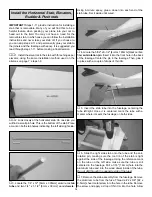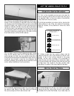
Slip two 5/32" [4mm] wheel collars onto the pushrod. Bend
the pushrod 90 degrees up at the mark. From the bend
measure up 3/8" [9.5mm]. Then, cut off the excess pushrod
wire. Install the wire into the hole in the servo arm using a
nylon FasLink.
❏
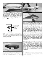
19. Re-center the other elevator. Bend the pushrod as
shown above to mate it with the first pushrod. Place the two
wheel collars as shown; put a drop of Great Planes Pro
Threadlocker
™
in the wheel collar screw hole and tighten the
wheel collar to the wires with a 6-32 x 1/4" [6-32 x 6mm]
socket head cap screw in each wheel collar.
You should now have all of the servo installation complete.
This leaves only the installation of the receiver/battery tray
into the fuselage. With all of the room in the fuselage you are
probably wondering why we don’t have the battery and
receiver mounted on a tray with the servos. The battery and
receiver need to be mounted where we have them in order
to achieve the proper balance without having to add weight
to the tail. This airplane has very clean lines and there is no
place we could have easily added tail weight without having
to stick lead to the tail or the fuselage. Though it is a bit
inconvenient, this installation utilizing a removable rear
former allows you to balance the plane without added
weight. Also, the removable front former allows access for
servicing the fuel tank.
❏
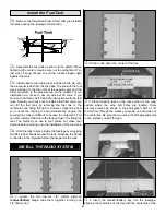
1. If the servos are not still connected to the receiver,
reconnect them. Plug the battery into the switch. Slide a
piece of heat shrink tubing over the connection or tape the
connections together to prevent them from coming loose in
flight. In addition to your servo connections, plug two 12"
extensions into the proper channels on your receiver for the
aileron and flaps. Mark the end of each extension for easy
identification of the flap and aileron.
❏
2. Install the receiver/battery tray using the two 4-40 x
5/8" [4-40 x 16mm] phillips pan head screws. In order to do
this you will probably need to disconnect the pushrods and
possibly remove the screws from the rear former. It really
depends on how large your hands are. Again, we understand
this is a bit inconvenient but once installed, you should not
have to remove the tray very often.
❏
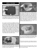
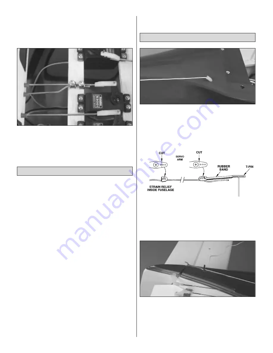
1. Here is a suggested method for installing the receiver
antenna. Other methods may also be acceptable. Drill a
5/32" [4mm] hole in the bottom of the fuselage. Be sure that
this hole does not interfere with the location of the receiver
tray. Insert a 3/4" length of fuel tubing into the hole. This will
protect the wire from being cut by the edge of the fiberglass.
❏
2. With a leftover servo arm, make a strain relief for the
antenna as shown. Install one arm onto the antenna wire,
sliding it onto the wire to within a few inches of the receiver.
Insert the antenna through the hole / fuel tubing in the
fuselage. Guiding the wire to the aft of the fuselage, install
the other arm onto the end of the wire as shown.
❏
3. The rubber band needs to be placed over an
attachment point at the end of the fuselage. We drilled a
5/64" [2mm] hole at the rear of the fuselage, tapped the hole
with a 2-56 tap and made a hook from a small length of
2-56 threaded rod. You might also consider installing a T-pin
in the bottom of the rudder or you can tape the rubber band
to the bottom of the fuselage.
Receiver Antenna Routing
Install the Receiver & Battery
28
Содержание Lancair ES
Страница 40: ......


