background image

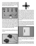
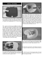
head cap screw into the arm and wheel collar. Slide the
metal  nose gear wire into the nylon nose gear bearing,
nose gear steering arm and engine mount. The coil of the
nose gear wire should rest on the nylon nose gear bearing.
Tighten the set screw against the flat spot in the nose
gear wire.

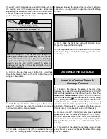
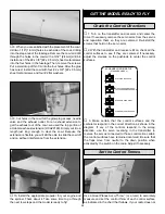
11. Cut one of the 24" [610mm] gray outer pushrod tubes

in half, making two 12" [305mm] tubes. Roughen one end of
the outer pushrod tube with sandpaper. Insert the end you
did not roughen into the hole in the firewall adjacent to the
nose gear steering arm (see the photo at step 13). Apply
glue to the roughened end of the outer pushrod tube and
insert it into the firewall, allowing the end of the tube to
extend approximately 1/4" [6mm] beyond the firewall. Do the
same with the second tube, inserting it into the hole in the
firewall for the throttle pushrod and through the hole in the
former, behind the firewall.

12. Locate a .074 x 36" [1.9 x 450mm] pushrod wire.

From the unthreaded end of the wire, cut a 15" [381mm]
long, unthreaded pushrod wire. Insert the pushrod into the
outer pushrod tube for the nose gear steering.

13. Locate the brass screw-lock pushrod connector

4-40 x 1/8" [4-40 x 3mm] socket head cap screw and nylon
retainer. Install it on the steering arm as shown in the
sketch, tightening the set screw to the wire pushrod. Be sure
to leave approximately 3/8" [9.5mm] of wire extending
through the screw-lock pushrod connector to allow for
adjustment to the steering.

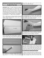
14. From the remainder of the 36" wire you cut, thread a

nylon clevis onto the threaded end of the wire 20 turns.
Install a silicone clevis retainer onto the clevis. Then, install
the pushrod into the outer pushrod tube for the throttle.
Install the clevis on the carburetor arm. Depending on the
exact location of your carburetor, you may need to make a
small bend in the wire to get free movement of the throttle
and pushrod.

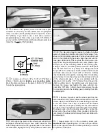
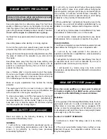
15. Carefully cut out the left and right halves of the ABS

nose gear fairing.

16. The next two steps are going to require you to work

rather quickly so be sure you have 6-minute epoxy,
microballoon filler and a small piece of waxed paper ready.
Mix 1/2 ounce of 6-minute epoxy. Add some microballoon
filler. Spread a small amount along the inside edges of both
the left and right fairing. Move quickly and don’t worry if it is
not too uniform. We are not filling up the fairing; only building
up the edges as shown in the photo at step 18.

21

Содержание Lancair ES

Страница 1: ...y the act of using the user assembled product the user accepts all resulting liability If the buyer is not prepared to accept the liability associated with the use of this product the buyer is advised...

Страница 2: ...l classic in an easy to fly model that will impress you by the way it flies and its good looks in the air We are sure you will get years of enjoyment from your Lancair For the latest technical updates...

Страница 3: ...deler is responsible for taking steps to reinforce the high stress points Remember Take your time and follow the instructions to end up with a well built model that is straight and true If you have no...

Страница 4: ...build the Lancair Drill bits 1 16 1 6mm 5 64 2mm 3 32 2 4mm 1 8 3 2mm 5 32 4mm 3 16 4 8mm 7 32 5 6mm 1 4 6 4mm 11 Blades 5 pack HCAR0211 3 Standard silicone tubing GPMQ4131 2 oz 57g Spray CA activator...

Страница 5: ...k TOPQ0208 Sapphire Blue TOPQ0226 Metallic Gold TOPQ0404 Fuse Fuselage Stab Horizontal Stabilizer Fin Vertical Fin LE Leading Edge TE Trailing Edge LG Landing Gear Ply Plywood Inches COMMON ABBREVIATI...

Страница 6: ...Silicone Clevis Retainer 1 4 40 x 1 8 Socket Head Cap Screws 4 2 56 x 5 8 Machine Screw 8 4 x 1 2 Sheet Metal Screw 5 6 32 X 1 8 Set Screw 3 6 32 x 1 4 Socket Head Cap Screws 2 4 x 5 8 Sheet Metal Sc...

Страница 7: ...Vacuum the parts and the work area thoroughly after working with fiberglass parts 1 If you have not done so already remove the major parts of the kit from the box and inspect for damage If any parts a...

Страница 8: ...cedure in the opening for the flap servo 9 On the top of the wing cut the covering away from the hole at the wing center section This hole is for the aileron and flap servo wires to come through into...

Страница 9: ...into the up position normal flying mode Install the servo arms onto the servo with the arm forward This will allow the servo to push against the flap control horn to keep the flap retracted When the f...

Страница 10: ...on servo cover over the servo making sure the servo arm is centered in the cut out Using the cover as a guide drill a 1 16 1 6mm hole into the wing skin through each of the holes in the cover Remove t...

Страница 11: ...the screw holes Drill through the marks you made with a 3 32 2 4mm drill bit Mount the nylon control horn to the aileron by inserting two 2 56 x 5 8 2 56 x 16mm machine screws through the control horn...

Страница 12: ...ner 2 Test fit the wing joiner into each wing panel making sure that it is not too tight Sand the joiner as needed to get a good fit 3 Apply 30 minute epoxy to both sides of the wing joiner the joiner...

Страница 13: ...eeds to be drilled through each of them You must follow this procedure If you try to drill a single 3 16 4 8mm hole the drill will tear the fiberglass Start by drilling a 1 8 3mm hole followed by a 5...

Страница 14: ...CA glue 8 Put the former back into the fuselage resting it against the four hardwood blocks Drill a 1 6 1 6mm hole into each of the blocks drilling through the holes you previously drilled in the form...

Страница 15: ...sing 6 minute epoxy glue a dowel into each end of the stab tube Set it aside until cured 4 Locate the 5 32 x 6 1 2 4mm x 165mm black carbon fiber anti rotation pin Insert it into the front hole in the...

Страница 16: ...sed for the elevator control These are the tubes in the white molded blisters on the fuselage The threaded end of the pushrod should be towards the elevator 13 Position a large nylon control horn on t...

Страница 17: ...baffling is necessary and is explained once you proceed to installing the cowl The engine mount and installation instructions for the engine mount will work for most 61 75 two stroke and 91 four strok...

Страница 18: ...he kit make sure you have adequate clearance for your spinner 8 Using the engine as a guide mark the four holes for the engine bolts on the engine mount This is easily accomplished with a Great Planes...

Страница 19: ...air outlet The air outlet is required for proper cooling with the Top Flite muffler If you are installing a standard muffler and have large cut outs in the cowl for the muffler you probably can skip i...

Страница 20: ...panel so they match the step in the fuselage that the cowl rests against This is easily done with the high speed rotary tool and the reinforced fiberglass cut off wheel 7 Using a 5 32 4mm drill bit d...

Страница 21: ...ate the brass screw lock pushrod connector 4 40 x 1 8 4 40 x 3mm socket head cap screw and nylon retainer Install it on the steering arm as shown in the sketch tightening the set screw to the wire pus...

Страница 22: ...t is also aligned straight ahead Tack glue the fairing to the wire with a small amount of CA 21 Mix another small amount of 6 minute epoxy and microballoon filler Coat the area around the fairing that...

Страница 23: ...center section on the bottom of the wing locate the cut outs for the landing gear Cut the covering away revealing the plywood mounting plates Seal the edges of the covering with your covering iron App...

Страница 24: ...g a mark on the wheel pant Remove the wheel pant from the axle Drill a 1 16 1 6mm hole through the mark the pin left on the wheel pant Put the wheel and the wheel pant back onto the axle Insert a 2 x...

Страница 25: ...accommodate the engine the cowling may make it difficult to access the carburetor You can also install a third line to the tank and use it for filling the tank The method you use is your choice but ma...

Страница 26: ...ing to be put in place in the wing saddle without the heads of the screws protruding into the wing 7 Set the receiver battery tray aside for now You will install it later 8 Locate the two plywood serv...

Страница 27: ...nd set the receiver battery tray to the side or you can leave things plugged in and do the following steps If you leave things connected you may wish to use masking tape to hold the receiver battery t...

Страница 28: ...ent them from coming loose in flight In addition to your servo connections plug two 12 extensions into the proper channels on your receiver for the aileron and flaps Mark the end of each extension for...

Страница 29: ...is installed inside of the cowl If you have any part of your engine or throttle linkage that conflicts with the baffle make those adjustments now 4 Place the baffle into the cowl The baffle should be...

Страница 30: ...ter and receiver and center the trims If necessary remove the servo arms from the servos and reposition them so they are centered Re install the screws that hold on the servo arms 2 With the transmitt...

Страница 31: ...it permanently inside Note Do not rely upon the adhesive on the back of the lead weight to permanently hold it in place Over time fuel and exhaust residue may soften the adhesive and cause the weight...

Страница 32: ...An unbalanced prop can be the single most significant cause of vibration that can damage your model Not only will engine mounting screws and bolts loosen possibly with disastrous effect but vibration...

Страница 33: ...3 miles of an airport without notifying the airport operator I will give right of way to and avoid flying in the proximity of full scale aircraft Where necessary an observer shall be used to supervise...

Страница 34: ...ly recommended Use of dual servos is also recommended for larger aircraft On board batteries shall be 1000 mAh up to 20 lbs 1200 mAh to 30 lbs 1800 mAh to 40 lbs and 2000 mAh over 40 lbs flying weight...

Страница 35: ...the propeller nut and spinner 18 Place your name address AMA number and telephone number on or inside your model 19 Cycle your receiver battery pack if necessary and make sure it is fully charged 20...

Страница 36: ...l Level the airplane when the model reaches the runway threshold modulating the throttle as necessary to maintain your glide path and airspeed When you re ready to make your landing flare and the mode...

Страница 37: ...F It s a great first scale model it s an aerobatic blast to fly the 61 5 span Shoestring is both with kit quality and easy ARF assembly as added bonuses All wood parts makes it light and lively dual a...

Страница 38: ...balance easily without measuring or marking and without the errors that fingertip balancing can cause You ll quickly pinpoint your plane s exact center of gravity Then you ll know at a glance whether...

Страница 39: ...e Purchased _________________________ Date Construction Started __________________ Date Construction Finished _________________ Finished Weight __________________________ Date of First Flight ________...

Страница 40: ......
Отзывы: