


❏
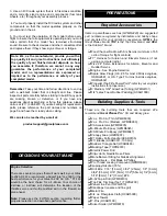
1. Place the wing on the fuselage. Measure from the aft
center of the fuselage to one wing tip and record the
distance. Measure from the same point to the opposite wing
tip, and compare it to the first measurement. If the
measurements are not the same, adjust the wing and
re-measure until they are equal. Place a mark on the wing
and fuselage so it can be repositioned accurately for the
following steps.
❏
2. Remove the covering from the holes in the wing
center-section where the wing bolts will pass through the
wing as shown in the photo for step 5.
❏
3. Bolt the wing to the fuselage using the
1/4-20 x 2"
nylon bolts.
Enlarge the holes if necessary to allow the
bolts to pass through the wing. Check the alignment of the
wing and enlarge the holes in the wing if necessary to allow
the wing to be shifted to match the alignment marks.
❏
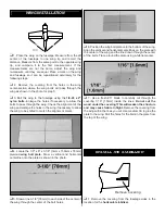
4. Locate the 1/8" x 6" x 3-1/8" [3mm x 150mm x 78mm]
plywood
wing bolt plate.
Draw a vertical and horizontal
centerline onto the plate as shown in the photo.
❏
5. Draw a line 3-1/8" [78mm] to each side of the center of
the wing through the center of the bolt holes.
❏
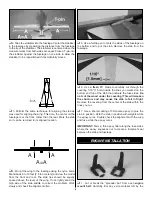
6. Position the wing bolt plate onto the bottom of the wing.
Align the vertical and horizontal centerlines on the plate with
the center of the wing and the line drawn through the center
of the bolts. Trace around the plate using a felt-tip marker.
❏
7. Use a fresh #11 blade to carefully cut through the
covering 1/16" [1.5mm] inside the lines.
Do not cut the
wood under the covering! This will weaken the structure
and may cause failure in flight.
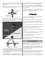
Remove the covering from
the wing within the lines you cut. Use medium CA to glue the
plate to the wing. Drill the holes for the bolts in the plate from
the top of the wing.
❏
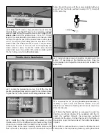
1. Remove the covering from the fuselage sides in the
location for the
horizontal stabilizer.
Remove Covering
INSTALL THE STABILIZER
WING INSTALLATION
7


